This document is intended to complement the
Understanding Servo Tune document, which more thoroughly explores the concept of servo tuning. There is no single proper way to do manual servo tuning, but the method outlined below provides a simple method to quickly determine gains that are in a reasonable range to provide a good response from the system.
Tuning Features of Measurement & Automation ExplorerOne way to tune an NI-Motion system is to open up the
Step Response and
Control Loop tabs as separate windows. To do this, follow these steps:
- In Measurement & Automation Explorer (MAX), go to Calibration»Servo Tune for your motion controller.
- Click and hold the Step Response tab
- Drag the mouse until the Step Response tab appears as a separate window
- Click the push pin icon at the top right of the window to keep the Step Response window open.
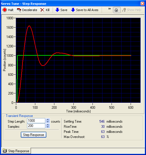
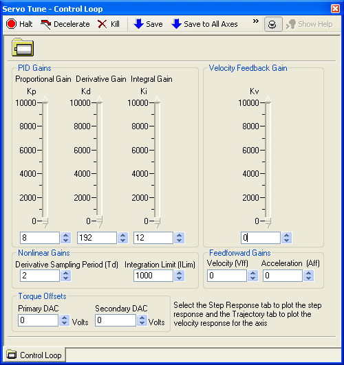
- Repeat these steps for the Control Loop tab. Arrange and resize the windows so that you can see them side by side as you tune your motor. Images of the windows are shown below for your reference.

 The Method of Tuning
Now that you have the windows arranged so that you can easily modify your control loop, and see the changes in the step response, take the following steps to tune your PID control system.
- Set all three PID parameters, Kp, Kd, and Ki to 0
- Start by tuning Kp. Set it to a number that is much lower than needed. If you are unsure, start with 1.
- Click the Step Response button to view a step response graph of your system. Step response plots are described in further detail in the Understanding Servo Tune document mentioned earlier.
- If the graph shows the parameter is:
- Too Low - Double the value of the parameter.
- Too High - Set the parameter to halfway between the current value and the previous value.
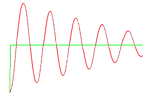
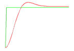
- Repeat steps 3 and 4 until you achieve a reasonable value for Kp. For most systems, this will mean that the response will approach the input, and oscillate continually about the input with a small amount of dampening. If the oscillation does not gradually decrease in amplitude as shown below, then the system is considered unstable. If this occurs, you may need to add a small amount of Kd while you are repeating steps 3 and 4 to increase Kp.

- After you arrive at a reasonable value for Kd, move on to Ki.
- Repeat steps 3 and 4 for Kd until you achieve a reasonable value for Ki. This parameter works on the integral of the position error therefore taking out offset error. Please use this parameter conservatively as it can introduce instability into the system.
See the
Understanding Servo Tune document for a tuning example.