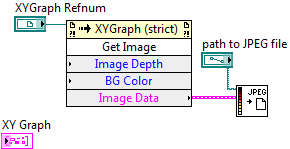
To save a control to a JPEG, PNG, or BMP file in LabVIEW 8.0 and later, follow these steps:
- Place your control on the front panel.
- On the block diagram, right-click on the control, and select Create » Invoke Node » Get Image.
- Go to Programming » Graphics and Sound » Picture Functions. Select RGB to Color.vi, and place it on the block diagram.
- (Optional) Create three numeric constants or controls, and wire one numeric to each input terminal on the RGB to Color function. These numbers are the proportion of red, green, and blue used in the color, and will be used to set the background color of the image of the control.
- (Optional) Wire the Color output terminal of the RGB to Color function to the BG Color input terminal on the invoke node.
- (Optional) Create a numeric constant, and wire it to the Image Depth terminal on the invoke node. Select an image bit depth (usually either 4, 8, 16, or 24), and type it into the constant.
- Go to Programming » Graphics and Sound » Graphics Formats, select one of the image file write VIs (Write JPEG file.vi, Write PNG file.vi, or Write BMP file.vi), and place it on the block diagram.
- Wire the Image Data output of the invoke node into the image data input of your chosen image write file VI.

To save a control to a JPEG, PNG, or BMP file in Labview 7.1 or earlier, follow these steps:
- Place your control on the front panel.
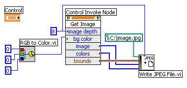
- On the block diagram, right-click on the control (for 3D ActiveX Graph controls, click on the green box, not the graph image), and select Create » Invoke Node.
- Right-click on the invoke node, and select Methods » Get Image Method.
- Go to Graphics and Sound » Picture Functions, select RGB to Color.vi, and place it on the block diagram.
- Create three numeric constants or controls, and wire one numeric to each input terminal on the RGB to Color function. These numbers are the proportion of red, green, and blue used in the color, and will be used to set the background color of the image of the control.
- Wire the Color terminal from the RGB to Color function to the bg color terminal on the invoke node.
- Create a numeric constant, and wire it to the image depth terminal on the invoke node. Select an image bit depth (usually either 4, 8, 16, or 24), and type it into the constant.
- Go to Graphics and Sound » Graphics Formats, select one of the image file write VIs (Write JPEG file.vi, Write PNG file.vi, or Write BMP file.vi), and place it on the block diagram.
- If you are using LabVIEW 7.0 or later, follow Step 8 of the LabVIEW 8.0 instructions listed above. For LabVIEW 6.1 and earlier, you must wire the value from the image depth numeric constant to the depth input terminal of your chosen file write VI. Wire the output parameters of the invoke node into the chosen image file write VI in the following fashion: image to flattened image data; colors to color table; bounds to rect. Lastly, create a constant or control for the file path of the image, and wire it to the path to file input terminal of the file write VI.

Additional Information
Note:
- The graphics and picture VIs needed for this are not available in the LabVIEW Base Development System. See related link below for information on upgrading LabVIEW.
- You can save several front panel controls to one JPEG, PNG, or BMP File by putting them into one cluster, and create a invoke node from the cluster.