For a basic description of how sinking and sourcing I/O work, please refer to the article "
What Is the Difference Between Sinking and Sourcing Digital I/O?".
To Connect a Sinking Input to a Sinking Output:Since a sinking input connected with a sinking output has a ground and a load, but no voltage source, a voltage source needs to be added to the circuit. This can be done by adding a "Pull-Up" resistor between the output of the I/O to a voltage source. This will add the voltage source that would otherwise be provided by the sourcing I/O and a resistor to prevent the voltage source from being shorted to ground. Below picture shows how to connect the resistor and voltage source along with the sinking input and sinking output.
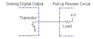
The resistor must meet two requirements. First, the resistance of the resistor must be high enough to provide an adequate load when the line is connected to ground by the sinking output. Second, the resistance has to be low enough to pull the line up from ground when the sinking output is off. Below are the calculations used to calculate the resistor value needed to use this circuit. These calculations assume that the voltage source is 24 V, a sinking input impedance of 5 kΩ, a maximum current of 20 mA through the resistor, and a threshold of 3 V.
Calculating the minimum resistor value using V = I * R:
V = I * R
⇔ R = V / I
⇔ R = 24 Volts / 20 mA = 1.2 kΩ minimum resistance
Calculating the maximum resistor value using the voltage divided equation:
Vn is Voltage at the node (Output)
Vt is Voltage source
R1 is resistance of the Sinking Input
R2 is resistance of the pull-up resistor
Using the voltage divider equation: Vn = Vt * ( R1 / ( R1 + R2 ) )
⇔ R2 = Vt * R1 / Vn - R1
⇔ R2 = 24 Volts * 5 kΩ / 3 Volts - 5 kΩ = 35 kΩ
Therefore, for this setup, the resistor needs to be between 1.2 kΩ and 35 kΩ .
Note: The digital output shorts to ground (turns the transistor on) when a 1 is written to it. This will cause the digital input to go low and read a 0. When the Digital Output is off (0), the voltage source is no longer grounded and the digital input will go high and read a 1. This is will cause logic to be inverted (i.e. a digital input will read a 1 if a 0 is written and read a 0 if a 1 is written).
To Connect a Sourcing Input to a Sourcing OutputWhen a sourcing input is connected to a sourcing output, a circuit with two voltage sources and one load is created. Since the input determines the "on" and "off" based on the voltage level at the input, a pull-down resistor needs to be added to pull the line to ground. Since having two voltage sources is a problem, there are two ways to configure the digital input's voltage source. The first is to give it the same source as the digital output. This is diagrammed in below picture.
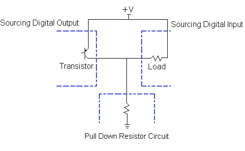
In this case, the pull-down resistor must be sized so that when the sourcing Digital Output is off, the voltage at the digital input registers at a logic low. Use the load resistance of the digital input to calculate this value. Additionally, the resistor must be sized so as to not violate the current limits of the Digital Input device.
The other case is to remove the supply voltage for the Digital input entirely. Below picture shows a diagram of this:
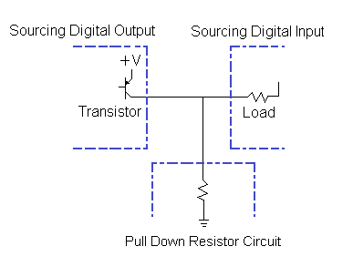
In this case, the pull-down resistor must be large enough to provide an adequate load when the line is connected to a voltage source by the sourcing output. The resistance of the resistor must also be small enough to prevent the line from "floating" (not being grounded) when the voltage source is disconnected by the digital output. Since there is not a voltage source attached to the digital input, the maximum resistance only needs to be high enough to prevent the leakage current from the transistor from pulling the line to V+. This value can be determined if the leakage current of the transistor is measured; however, since this current is so small, a resistance with a value less than 100 kΩ should be more than sufficient. Below are the calculations used to calculate the resistor value needed to use the circuit in fig 3. The calculations below assume a source voltage of 24 V and a maximum current of 20 mA through the resistor.
Calculating the minimum resistor value using V = I * R:
V = I * R
⇔ R = V / I
⇔ R = 24 Volts / 20 mA = 1.2 kΩ minimum resistance
For this setup, the resistor needs to be at least 1.2 kΩ and less than 100 kΩ .