Single-Ended Quadrature Encoder
A standard single-ended quadrature encoder has up to 3 channels— A, B and Z.
There are also 3 types of encoding possible, X1, X2 and X4.
These are explained in the Additional Information section below.
To use a quadrature encoder with an NI DAQ card, connect channels A, B and Z to the counter's
SOURCE,
AUX and
GATE pins, respectively. To find the pinout for a specific DAQ card, right click the card in NI MAX and select
Device Pinout.
Differential Quadrature Encoder
Differential quadrature encoders typically have 2 signals for each channel, where the second signal is the inverse of the first. These are often labelled either as plus and minus, or the second channel is specified as the inverse or compliment. Most NI DAQ cards do not support differential encoder measurements. The alternative would be to use the NI-9411's differential digital inputs to measure the encoder's differential outputs.
However, differential encoders can be used in the same way that a single-ended quadrature encoder is used. The A, B and Z index channels can be connected to the
SOURCE,
AUX and
GATE pins on the DAQ counter. This will allow the encoder to operate as though it is a single-ended device. This connection can be made with either the plus or minus signals. The connected signal should be referenced to ground and the remaining signal can be left disconnected.
Additional Information
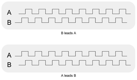
Channels A and B are both output by the quadrature encoder 90 degrees out of phase with each other. Images of the A and B channel outputs are shown below. The direction of rotation is determined by which phase leads. When phase B leads A, then the shaft is rotating in the counter-clockwise direction and vice-versa.
The types of encoding (X1, X2 and X4) simply determine what edges of channel A and B signals the counter increments/decrements on. For more information about these types of encoding, see page 7-15 of the
M Series User Manual.
It is also important to note that when setting up a counter task in DAQmx, the PPR (Pulse per Revolution) is a property of the encoder itself and its value will not change with the selected encoding type. DAQmx will internally adjust its calculations for X2 and X4 encoder measurements. There is no need to scale this value by 2 (for X2) or by 4 (for X4).