Templates for NI myRIO provide an inclusive Multisim schematic with the available inputs and outputs and an Ultiboard layout with the connectors and outline.
Multisim comes installed with the NI myRIO single MXP and dual MXP templates. The process for using these is outlined below:
-
Within Multisim select: File » New…
-
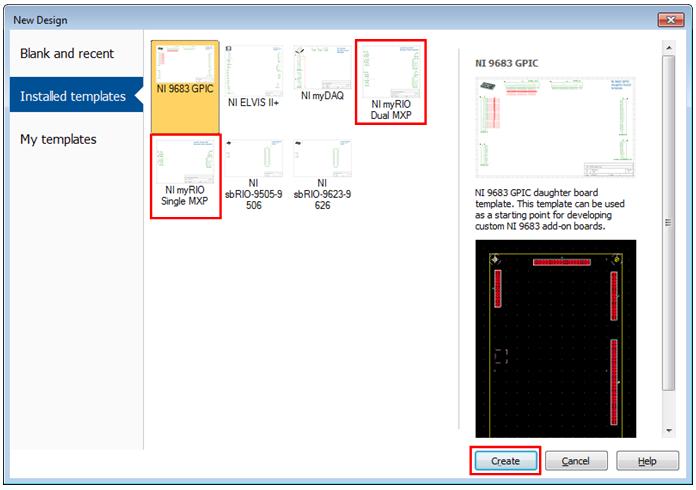
This opens the New Design window as seen in figure 6. Within this dialog select installed templates and we can select either the NI myRIO Dual MXP or the NI myRIO Single MXP. We also get a description and preview of the template design.

Figure 6 – Multisim new design window
-
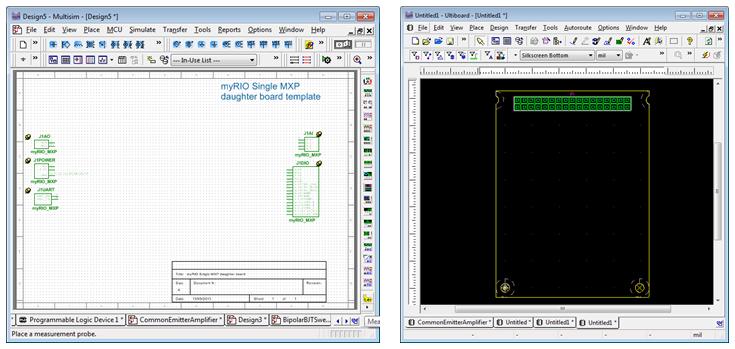
Click Create and Multisim will open both the schematic and a Ultiboard layout which will form the template of our design. From here, in Multisim you can place the components you will be using and in Ultiboard you can create the layout of these components around the built in connector and outline. Figure 7 shows an image of the schematic and layout for the Multisim NI myRIO Single MXP template.

Figure 7 - The Multisim template for a Single MXP daughter board comprising of a Multisim schematic with the available IO and an Ultiboard layout with the connector and board outline.
The templates for the board-only NI myRIO are installed with Multisim. If using the enclosed NI myRIO the template is available on NI Labs details of which can be found at Multisim MXP Daughter-board Templates for myRIO.
Two templates are attached below and another template can be found at Multisim MXP Daughter-board Templates for myRIO.