Complete the following steps to overcome ghosting:
- Select a transducer with lower source impedance.
- Reduce sampling rate and increase interchannel delay to allow enough settling time for the amplifier. See Increasing DAQ Interchannel Delay for Longer Settling Times for more details.
- Implement a voltage follower or buffer circuit to decrease source impedance to less than 1 kΩ. See Eliminate Ghosting on Adjacent Input Channels by Decreasing Source Impedance for more details.
- Arrange signals to minimize voltage swings between channels.
- Choose the high-impedance channel as the first channel in the scan list.
- Note: This will only help if you are not sampling in round-robin mode.
- Avoid multiplexing – sample one channel at a time or switch to a simultaneous sampling DAQ device.
- Read the desired channel twice by implementing a "dummy channel". Why this reduces ghosting and how it is implemented is explained below in "Why Does Ghosting Occur?".
- Note that this feature (duplicate channel readings) is supported on multiplexed X or M series DAQ devices but not on C Series Modules.
If you are experiencing other types of signals in your samples such as extra frequencies being added in, or other offsets to your signal even when sampling only one channel, you might be experiencing crosstalk on your signal. See
Unexpected Voltages, Floating or Crosstalk in Analog Input Channels for more information on crosstalk and troubleshooting steps.
Additional Information
Why Does Ghosting Occur?
High source impedance on a scanned channel causes its settling time to increase. The small internal capacitance on the analog-to-digital converter (ADC) combines with the high source impedance to create a low pass filter. As the source impedance increases, so does the time constant of this filter and thus its settling time. A simplified diagram is below:
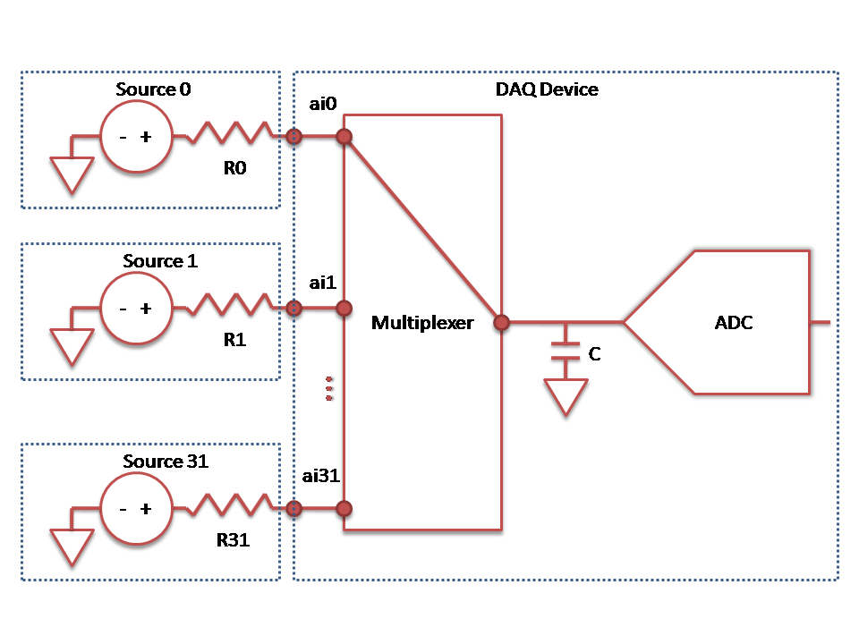
As the multiplexer switches from one channel to the next, the capacitor C starts to charge from the voltage of the previous channel to the voltage of the connected channel. If RX is too large, C will not be charged (or discharged) to the correct voltage and will show remnants from the previously scanned channel when the measurement is taken by the ADC. This incorrect reading is called ghosting. It is also often incorrectly labeled crosstalk.
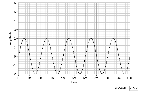
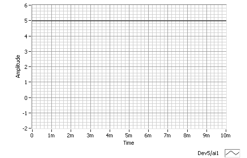
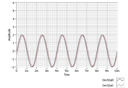
Let's take an example: Assume R0 is small (< 1 kΩ) and source 0 is a sine wave with an amplitude of 2 V with no offset. In addition, assume R1 is large ~100 kΩ and source 1 is held at a constant 5 V. When measuring each signal individually, you do not switch between channels of the multiplexer and will see the following:
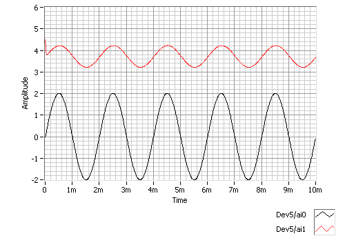
However, when both channels are scanned the sine wave is reflected onto channel 1:
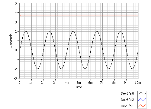
This same issue will occur if no signal is connected to a channel since RX will essentially become infinite. If source 1 is completely disconnected from ai1 and both ai0 and ai1 are still scanned, you will see the following:
It is incorrect to suggest that scanning a grounded channel before a high-impedance channel will reduce ghosting by allowing the capacitor to discharge to ground. The time it takes for the voltage at the ADC to reach the correct level is related to the difference between the previous channel and the current channel, not just the current charge of the capacitor. For this reason, it is best to arrange signals to minimize voltage swings between channels.
If ground (0 V) is farther away from the voltage of the high-impedance channel than the voltages of the other scanned channels, it will actually take longer for the high-impedance channel to reach the desired level. Grounding the channel before a high-impedance channel is only useful if the high-impedance channel is closer to 0 V than the other scanned channels.
In the previous example, grounding the channel scanned before the high-impedance channel does not allow the high-impedance channel to take a correct measurement. Below is a graph of the preceding example with a grounded channel (ai2) added between the low-impedance channel and the high-impedance channel. Note that the actual voltage of the high-impedance channel is supposed to read 5 V.
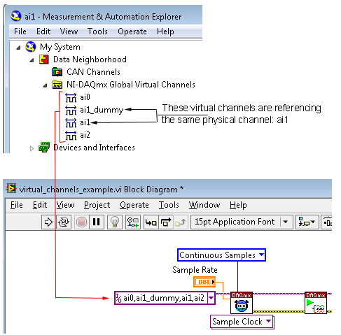
As mentioned above, large voltage swings on adjacent channels will increase the voltage settling time on these channels resulting in inaccurate reading. In order to reduce the voltage swings between two channels, you can add an additional "dummy" channel before the channel that you are trying to get an accurate reading from. The dummy channel will allow for the voltage to be read twice on the same channel, which would reduce the voltage swing between two subsequent channels, resulting in a more accurate reading.
For example, the voltage on ai0 is 10 V and the voltage on ai1 is 2 V. By scanning a dummy (ai1_dummy) channel before ai1, you will allow more time for the voltage at the ADC to reach the correct level which would reduce the ghosting effect between ai0 and ai1. A virtual "dummy" channel can be created in Measurement & Automation Explorer, and then added to the list of scanned channels in LabVIEW as seen in the figure below:
Note that the aggregate sample rate of all channels (dummy channels included) should not surpass the maximum aggregate sample rate of the device.