If you are unfamiliar with what the Open-Drain or Push-Pull method means, please see the following documentation on
choosing between Line Driver, Open Collector, and Push Pull Encoders for NI devices.First, check your device's user manual to ensure that your device supports both push-pull (also called active driver or sourcing) and open-drain (also called open collector or sinking). The user manual should also contain what the default state for your device is.
Note: Not all NI-DAQ Devices can be configured as sinking or sourcing. Most devices listed as bidirectional sinking/sourcing digital devices must be wired in a particular way to perform as either sinking or sourcing devices, as discussed in the KnowledgeBase article:
Configuring the NI 940x Modules for Sinking or Sourcing Digital Outputs. See your device's user manual for more information on correct wiring of digital lines.
Using NI-DAQmx to change to Push-Pull Operation
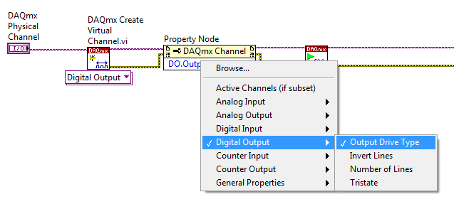
In LabVIEW you can use a channel property node to configure the various channels on a device. After placing the DAQmx channel property node on the block diagram, click on it and select
Digital Output»Output Drive Type as shown in the following example code:

Right click on the
DAQmx Channel Property and go to
Select Filter>>Show All Attributes to show the available properties, even if the required channel reference is not provided. In LabVIEW, the channel property DO.OutputDriveType will not be visible unless the DAQmx Channel Property node is referenced to a device that supports different output drive types and "Show All Attributes" is selected.
Right click on the
input node of the DO.OutputDriveType property, and go to
Create»Constant. The term "Open Collector" is the DAQmx equivalent to open-drain, and "Active Drive" is the DAQmx equivalent to push-pull.
This functionality will work the same with LabWindows CVI, Microsoft Visual Studio, and any other language that can be programmed with the NI-DAQmx drivers. To locate the required function call, search for "Output Drive Type" in the DAQmx API help.
Using NI-DAQmx Base to change to Push-Pull Operation
If you are using NI-DAQmx Base, you can set this property in the NI-DAQmx Base Configuration Utility. There is no way to programmatically set the output drive setting in NI-DAQmx Base. The Configuration utility can be found in the NI-DAQmx Base folder (typically
Hard Drive»Applications»National Instruments»NI-DAQmx Base on a Mac, or
/usr/local/natinst/nidaqmxbase/bin on Linux). Complete the following steps to change the output drive setting:
- Select Create New Task
- Choose Digital I/O as the acquisition task type and give the task a name
- After the task is created, select the Voltage Tab.
- In the Voltage Tab, there is a DIO Voltage Level option. For open-drain, use the 0-5V option. For push-pull, use the 0-3.3V option.
Change Operation in Visual Studio
In Visual Studio you can use this equivalent code to configure various channels on a device.
Open Collector:
myTask.DOChannels.All.OutputDriveType = DOOutputDriveType.OpenCollector
Active Drive:
myTask.DOChannels.All.OutputDriveType = DOOutputDriveType.ActiveDrive
Change Operation in Python
The example below demonstrates how to change a device called "Dev1" to Active Drive on port 0 line 7.
import nidaqmx
from nidaqmx.constants import DigitalDriveType

with nidaqmx.Task() as task:
	do_channel = task.do_channels.add_do_chan("Dev1/port0/line7")
	print("Mode before: ", do_channel.do_output_drive_type)
	do_channel.do_output_drive_type = DigitalDriveType.ACTIVE_DRIVE
	print("Mode after: ", do_channel.do_output_drive_type)
Refer to
[External] NI-DAQmx Python Documentation for more information.
Additional Information
Changing the data collection operation so you do not have to set it manually again is related to the Power-On States parameter. Refer to the manual for your device to see if it supports programmable Power-On States.
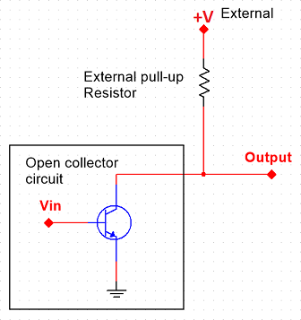
Open-drain (MOSFET) or open collector (BJT) are circuits that use a single resistor with a pull-down or pull-up resistor to transition a digital line between a high and a low. Basically, the circuit has a resistor between the path to ground or the path to 5V. So when the transistor is off, the line will float to the high or low voltage.

Consider the case of using a BJT with a pull-up resistor. During a high, there is 0V to the base of the BJT. This causes an open circuit on the BJT which causes the line to be pulled high by the pull-up to 5V. With a high impedance load, you should see a full 5V across the load (the pull-up is 4.7k Ohm). During a low, there is 5V generated to the base of the BJT. This shorts the circuit to ground and causes all the current flow from the pull-up circuit to flow directly to ground. This gives you the 0V across the load.
The push-pull, also referred to as the active-drive, works quite a bit differently. This circuit uses two transistors to determine between a high and low logic. For this system, there is typically two BJT's with one being an NPN and the other being PNP. Take a look at the below schematic:
As you can see from the Push-Pull circuit, there are two transistors used to drive the output between the 5V or ground. When Vin is low, the bottom BJT will be on and the top BJT will be off which will result in 0V across the load. When Vin is high, the top BJT will be on and the bottom will be off which will result in 5V across the load.
Note: The NI-USB 6008 always has an output drive-type of open-drain and cannot be changed to push-pull.