The input impedance specification may read >10 GΩ, 10 MΩ or >10 GΩ, 1 MΩ for your digital multimeter. This means that the impedance is selectable in those ranges and can be either high impedance (greater than 10 GΩ), 10 MΩ impedance, or 1 MΩ impedance, depending on the device.
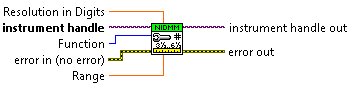
Note: Auto Range must be disabled to configure the device for an input resistance that is not supported on all voltage ranges (as shown in chart found in
Issue Details above). This can be done by specifying the desired range manually using the Range input of the
niDMM Config Measurement VI . This VI is shown below:
You can select the input impedance in LabVIEW using the NI-DMM property node by following the steps below:
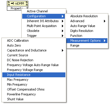
- Place a niDMM Property Node on the Block Diagram.
- After you place the property node on the block diagram, select Configuration » Measurement Options » Input Resistance as shown below.
- To get property information, which will indicate what the input impedance is currently set to, right-click the node and select Change All to Read from the shortcut menu. To set property information and control the input impedance, right-click the node and select Change All to Write from the shortcut menu.
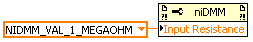
- Now, you can create a constant or a control that will let you select between 1 MΩ, 10 MΩ, and >10 GΩ as shown below. Note: This property node should be wired in after the niDMM Configure Measurement VI to ensure this is set accordingly.