The NI Camera Link I/O Extension Board is not capable of operating on its own without a frame grabber and therefore will not show up in either NI MAX or in Windows Device Manager. You will see your frame grabber in both of these places, but not the Camera Link I/O Extension Board.
Refer to the information below to set up the I/O Extension Board in hardware and software.
Hardware Setup
- Use the NI Camera Link I/O Extension Board User Manual to connect signals
- Note that there is a 37 pin breakout option and 44 pin breakout option
- You do not need to connect power to the Camera Link I/O Extension Board unless you want to use the 12V and 5V outputs on the breakout board
The NI Camera Link I/O Extension Board allows you access to the isolated I/O and external I/O (TTL signals). For the PCIe-1429, PCIe-1430, and PCIe-1433, external line 0 is the SMB connector on the front of the frame grabber and the Camera Link I/O Extension Board provides access to external I/O lines 1-8.
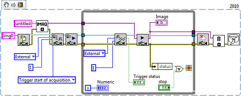
Software Setup
- Use the IMAQ Configure Trigger 3 VI and IMAQ Trigger Read2 VI to set up and read your trigger
- Inputs Line Number and Trigger Number both correspond to the TTL or ISO line with that number on the Camera Link I/O Extension Board.
- For example, if you wire in External and 1 to Trigger Type and Line Number, respectively, you are referencing TTL I/O 1 on the Camera Link Extension Board.
You can also use TTL I/O 1 to trigger the start of your acquisition.
 Note:
Note: Ensure that your camera is in a triggered mode and not a free run mode.