You can generate pulses and send them to the CC lines if your card supports this ability. However, you cannot do this directly. When generating triggers or pulses using the IMAQ Trigger Drive2 VI or the IMAQ Generate Pulse3 VI, you must select a line that was previously configured to route to the desired CC line. To find out what routing is supported on your board, refer to
Which NI Camera Link Boards Support Routing to the Camera Control (CC) Lines?.
Once you know what your card supports, you can configure this routing in Measurement & Automation Explorer (MAX) on the
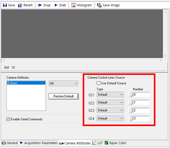
Camera Attributes tab under the
Camera Control Lines Source section as displayed below:
(If you use MAX version 18.0 or later, please refer to
How Can I Route a Trigger Signal Directly to My Camera Link Camera? article.)

Uncheck the
Use Default Source check box. Select the desired CC line and choose what to route to it. Save this configuration. Once you have done this, you may use the IMAQ Trigger Drive2 VI or the IMAQ Generate Pulse3 VI and send a trigger or pulse to the line previously configured to route to the desired CC line.
For example:
If you are using the PCI-1433 and you would like to send a single, software timed, 1 ms pulse to CC2 using the IMAQ Generate Pulse3 VI you would first configure CC2 in MAX. In the Camera Attributes tab, uncheck the
Use Default Source check box. For CC2, you may select
External for the Type. Then you may select a line Number
0 (SMB connector).
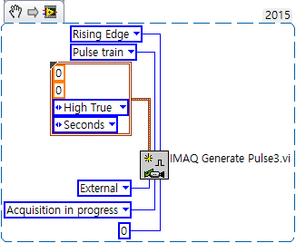
After this, you may go into LabVIEW and select the following input parameters for the IMAQ Generate Pulse3 VI:
Rising Edge for Signal polarity, Single pulse for Pulse Mode, External for Signal Type, Immediate for Status Signal and 0 for Signal Number. For the Pulse Parameters, 0 for Pulse Delay, 0.001 for Pulse Width, High True for Pulse Polarity and Seconds for Units.
