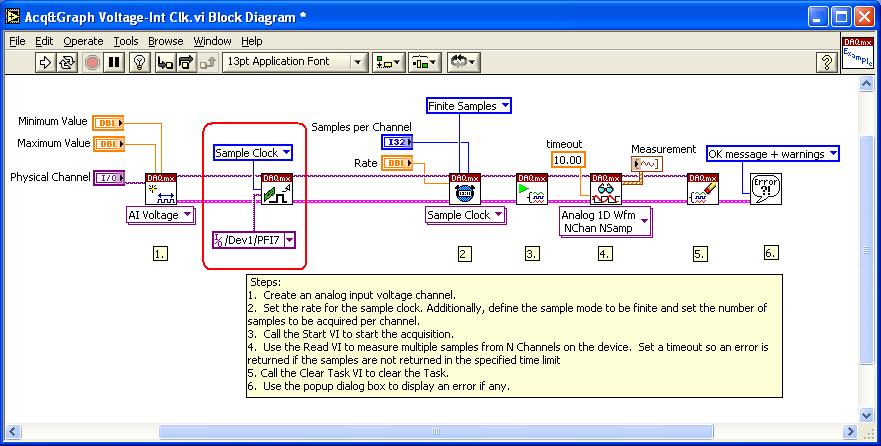
There are two steps to solving this problem. The first involves locating the terminal of your DAQ device from which you can access this signal. The second involves programming the board to route the internal sample clock to this terminal.
- On most Multifunction DAQ devices, the AI Sample Clock can be accessed through a PFI line. To know which PFI terminals you can use to route the AI Sample Clock, please refer to the Device Routes tab in MAX.
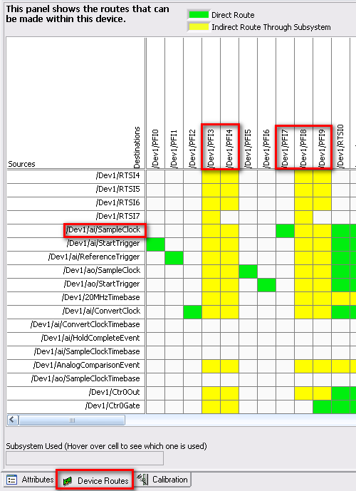
On this particular device, the AI Sample Clock can be routed to PFI 3,4,7,8 or 9. If a panel in the routing table is yellow, this indicates that a subsystem is used to make this connection. To view which resources will be used, move the cursor to a panel on the routing table and view the Subsystem Used box. On the other hand, if a panel is green, this indicates that there is a direct route between those two terminals so no subsystems are used. So for this example, PFI7 would be the best option for routing the sample clock to as it will not hold up any resources on your device.
- There are two methods for internally routing this signal to a PFI line.
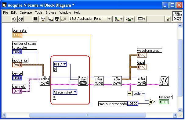
- Traditional NI-DAQ: You will need to use the Route Signal VI which can be found in the NI Measurements»Data Acquisition»Calibration and Configuration palette.
- NI-DAQmx: You will need to use the DAQmx Export Signals VI which can be found in the NI Measurements»DAQmx - Data Acquisition»DAQmx Advanced Task Options»DAQmx Export Signals palette.