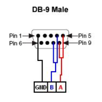
Since the receiving device only has three available pins, its user manual should have specific instructions regarding the proper wiring, so be sure to check there first to see if there are any caveats in communicating to your device.
Otherwise, since EIA 485 is a standard, devices that claim to use this protocol should require the following wiring to achieve full communication (also reference the embedded image of a schematic):

- Pins 5 and 9 of the DB 9 Male connection should be jumpered together and wired to terminal A of your device.
- Pins 4 and 8 of the DB 9 Male connection should be jumpered together and wired to terminal B of your device.
- Pin 1 of the DB 9 Male connection should be wired directly to terminal GND
Note: If you're unfamiliar with pins of a DB 9 Male connector, please reference the
Serial Quick Reference Guide.
Once this external wiring has been completed, configuration of the software that controls the NI USB-485 device is required. Complete the following steps to configure the software:
- Install the NI-Serial driver on your computer and verify the hardware is recognized by Windows.
- Open Measurement and Automation Explorer and under the expandable tree for Devices and Interfaces, left-click to expand the Serial & Parallel tree.
- Identify the COM port that is for the NI USB-485 device and highlight that item by left-clicking on it.
- In the configuration window to the right, you should see a tab at the bottom labeled Advanced. Select this tab and disable the Bias Resistors Enabled option by deselecting the check box. Select 2 Wire Auto for Transceiver Mode.
These changes should now allow your NI USB-485 to communicate to the EIA 485 compliant device with only the three pins available.