Hardware Setup
-
Connect your SHC68-C68-RDIO2 Cable to Connector0.
-
Connect your SHC68-68-RMIO Cable to Connector1.
-
Connect your SCB-68 HSDIO to your SHC68-C68-RDIO2 Cable.
-
Connect your SCB-68A to your SHC68-68-RMIO cable.
-
Connect the A type connector of the USB cable to your PC, and the B type connector to the device.
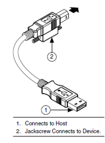
Figure 2. USB Connections
-
Connect power to your USB R Series device and turn on the power switch on the back of the device.
-
The device now shows up in Measurement & Automation Explorer (MAX) as seen in Figure 3.
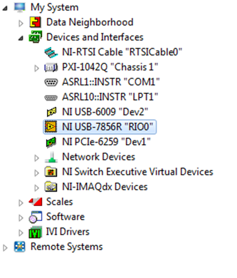
Figure 3. MAX Tree View
Note: If the device shows up in MAX with the standard USB icon (  ), then the NI-RIO driver needs to be installed or repaired.
-
If the device does not show up in MAX, double check the LEDs on the front panel of the USB R Series device to determine if the device is powered, the USB is ready, and that there are no errors.
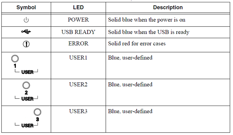
Table 1. LED Description for USB R Series Devices
Now your device is ready to be used in LabVIEW!
Project Setup in LabVIEW
We are going to set up a new project in LabVIEW and acquire data from an analog channel.
-
Launch LabVIEW to display the Getting Started Window
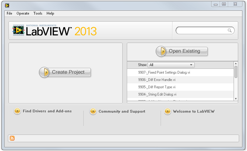
Figure 4. LabVIEW Getting Started Window
-
Left-click the Create Project button or left-click File»Create Project»Blank Project.
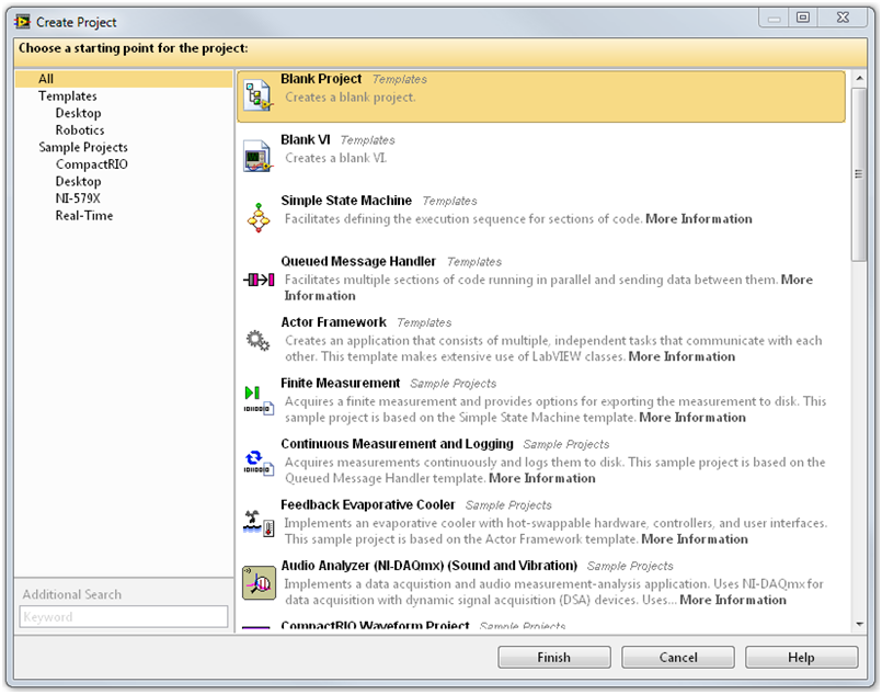
Figure 5. Create Project Window
-
In the project window, right-click My Computer»New»Targets and Devices …
You can add the target in one of two ways. If you have the device connected and discovered in MAX, you can use the Existing target or devices option. If you do not have the target connected at the moment, you can use the New target or device option.
-
Select Existing target or device»Discover an existing target(s) or device(s).
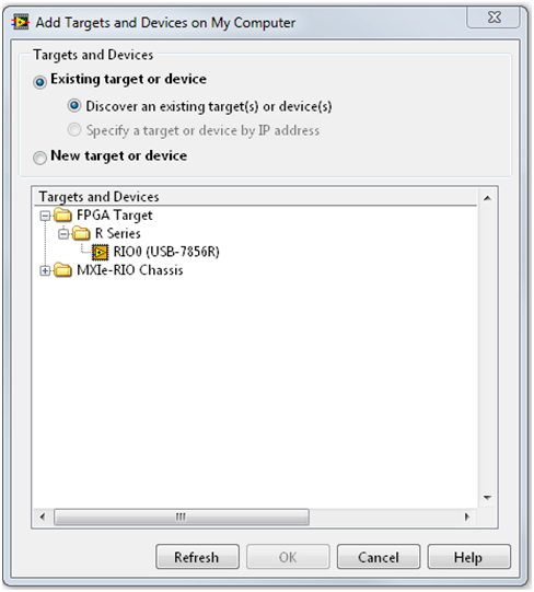
Figure 6. Add Targets and Devices Window
-
Select New target or device.
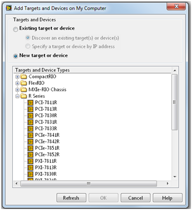
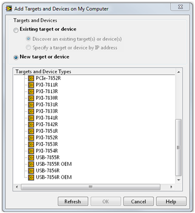
Figure 7. New target or device selection
-
Now that the target is added, you need access to the FPGA I/O. Right-click FPGA Target»New»FPGA I/O.
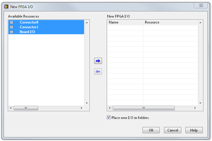
Figure 8. Add FPGA I/O
-
Right-click the arrow and click OK. Now your project contains new folders labeled Board I/O, Connector0, and Connector1 as seen in Figure 9.
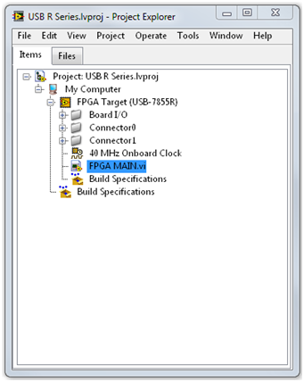
Figure 9. FPGA I/O in LabVIEW Project Explorer
-
Right-click FPGA Target»New»VI.
-
Left-click File»Save As …»RT MAIN.vi.
This is a good starting point for a new project. Now it’s time to implement one of the examples.
Data Acquisition
-
The attached folder Getting Started has a Getting Started – USB R Series.lvproj. The project can also be found through NI Example Finder launched by selecting Help >> LabVIEW Help... or through the path:
C:\Program Files (x86)\National Instruments\LabVIEW XXXX\examples\R Series\Device Specific\USB Devices\Getting Started\Getting Started - USB R Series.lvproj
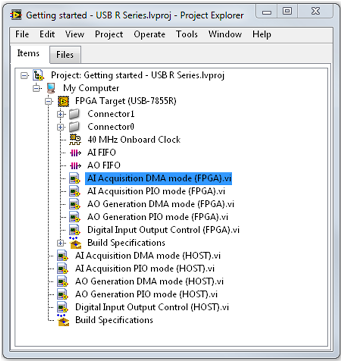
Figure 10. Getting Started Project Explorer
-
We are going to focus on the AI Acquisition DMA mode FPGA and HOST VIs.
-
Compile AI Acquisition DMA mode (FPGA).vi by right-clicking the VI in the Project Explorer»Create Build Specification.
-
This creates a Build Specification.
-
Right-click the Build Specification»Build.
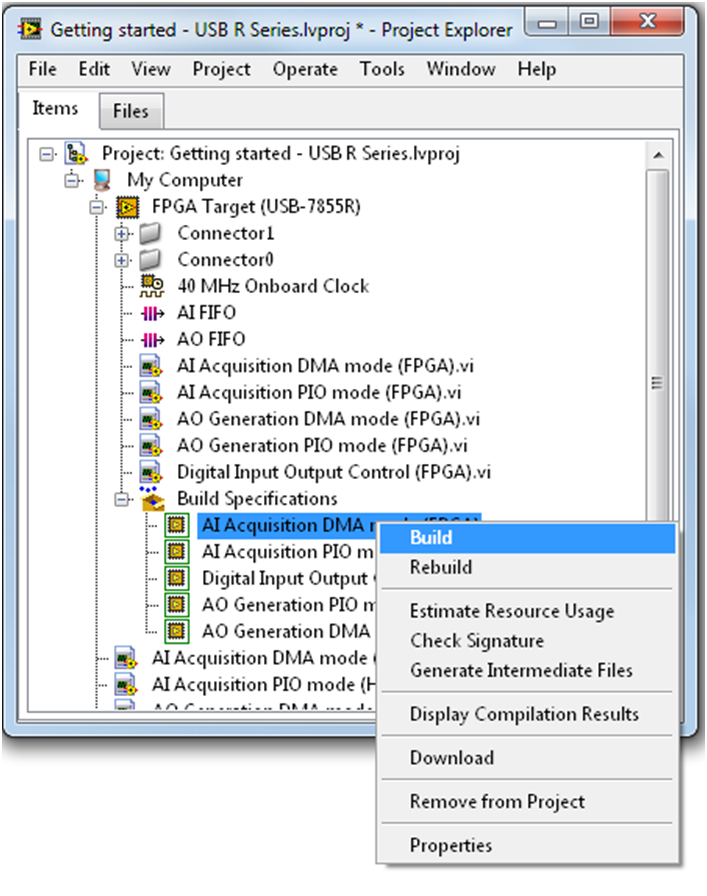
Figure 11. Create Build Specification
-
There are three options to compile. If you installed the Xilinx Compile Tools, you can use the first option, Use the local compile server.
-
After you have compiled the AI Acquisition DMA mode (FPGA).vi, you can run the AI Acquisition DMA mode (HOST).vi
-
Set the resource name to the RIO resource name as seen in MAX. For this example, it would be RIO0.
-
You can use the Configure AI tab to set up the AI Acquisition and the Read DMA AI tab to see the actual data.
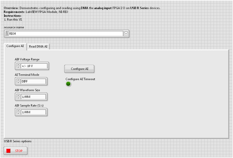
Figure 12. Front Panel of AI Acquisition DMA Mode (HOST).vi
Congratulations! Your USB R Series device is successfully up and running. For a more in-depth tutorial on using the full functionality of your device, refer to Related Links below.