Interactively Configuring an EPICS Server I/O Server
-
Open and save a new LabVIEW project
-
Add two virtual folders to the project
-
Right click My Computer and select New » Virtual Folder
-
Name one folder Client and the other Server
-
Add a library into each folder
-
Right click Client and select New » Library
-
Right click Server and select New » Library
-
Respectively title the libraries Client Library and Server Library
-
The project should now look similar to Figure 1
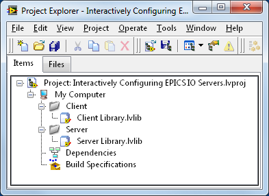
Figure 1: Preparing the LabVIEW Project
- Create the Shared Variables listed in Table 1
-
Right click Server Library.lvlib and select New » Variable
-
Under the Variable tab, apply the parameters specified in Table 1
-
The Shared Variable Properties window should look similar to Figure 2
|
Name
|
Variable Type
|
Data Type
|
|
Amplitude
|
Network-Published
|
Double
|
|
Frequency
|
Network-Published
|
Double
|
Table 1: Server Shared Variables
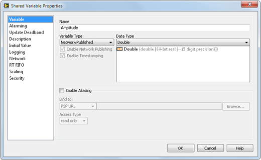
Figure 2: Shared Variable Properties Window
- Add a new I/O Server to the Server Library
-
Right click Server Library.lvlib and select New » I/O Server
-
Select EPICS Server » Continue... and the window in Figure 3 will appear
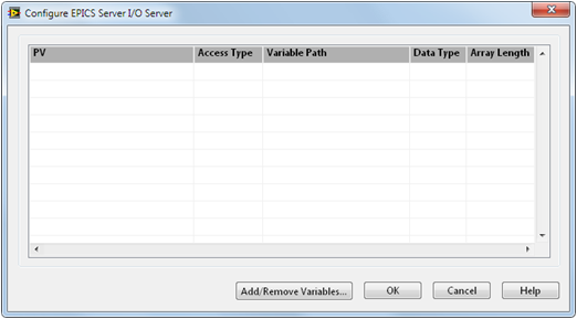
Figure 3: Configuring an EPICS Server I/O Server
- Add the shared variables created in Step 4 to the I/O Server
-
Select Add/Remove Variables...
-
Browse to Server Library.lvlib and select the two variables
-
Select Add >> to add the variables to the I/O Server
-
The configuration window should look similar to Figure 4
-
Select OK
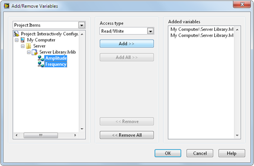
Figure 4: Adding New Variables to an EPICS Server I/O Server
- Note the EPICS Process Variables (PVs) have been created for both shared variables
-
At this time, take note of the Process Variable names, they will be needed in a later step
-
The window will look similar to Figure 5, however PV names and paths will be different
-
Select OK
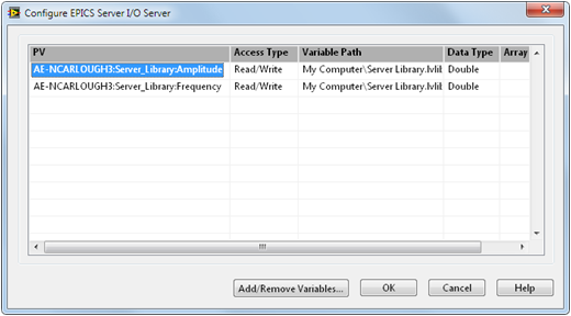
Figure 5: Newly Created EPICS Process Variables
Building an EPICS Server VI
The server VI in this tutorial will publish amplitude and frequency parameters to the EPICS network. These parameters will be read by a client and then fed into a function generator.
For more information on the differences between EPICS Servers and EPICS Clients, see the Developer Zone Article, Introduction to EPICS or the Argonne National Laboratory website.
-
Add a new VI to the Server virtual folder
-
Right click Server and select New » VI
-
Save the VI as EPICS Server.vi
- Build a front panel similar to that shown in Figure 6
-
Add two numeric controls (preferably knobs)
-
Add a boolean stop control
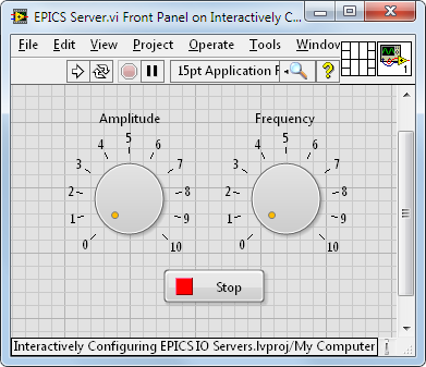
Figure 6: EPICS Server VI Front Panel
- Build the block diagram shown in Figure 7
-
Add a While Loop and wire the Stop Button to the conditional terminal of the loop
-
Add the Amplitude and Frequency Shared Variables to the block diagram
-
Right click on the variables and select Access Mode » Write
-
Wire the Amplitude and Frequency controls to the corresponding shared variables
-
Add a 100 ms Wait to the loop to give the processor time for other tasks
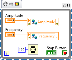
Figure 7: EPICS Server VI Block Diagram
Interactively Configuring an EPICS Client I/O Server
-
Add a new I/O Server to Client Library
-
Right click Client Library.lvlib and select New » I/O Server
-
Select EPICS Client » Continue...
-
The "Configure EPICS Client I/O Server" window will appear
- Add new records to the I/O Server
-
Click the Add Records button twice to add two new records in the PV List
-
Replace the default PV names with the names generated by the Server I/O Server
-
Change the data types of both Process Variables to Double
-
The window should now resemble Figure 8, select OK
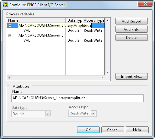
Figure 8: Configuring the EPICS Client I/O Server
- Create corresponding Client Bound Shared Variables
-
Right click EPICS Client1 and select Create Bound Variables...
-
The "Create Bound Variables" window will appear, browse to Client Library.lvlib
-
Under EPICS Client1, select the VAL fields for both variables
-
Click the Add >> button to move the fields to the Added Variables list
-
The window should now resemble Figure 9, select OK
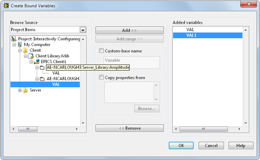
Figure 9: Creating Bound Shared Variables on the EPICS Client
- Rename the bound variables
-
After completing step 2, the "Multiple Variable Editor" window will appear
-
It may be desirable to change the names of the variables to something more meaningful
-
Change the variable names by double clicking in the Name field and typing the new name
-
The window should now look similar to Figure 10, select Done
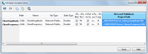
Figure 10: Changing Variable Names With the Multiple Variable Editor
Building an EPICS Client VI
- Add a new VI to the Client virtual folder
-
Right click Client and select New » VI
-
Save the VI as EPICS Client.vi
- Build a front panel similar to that of Figure 11
-
Add a waveform chart
-
Add a boolean stop control
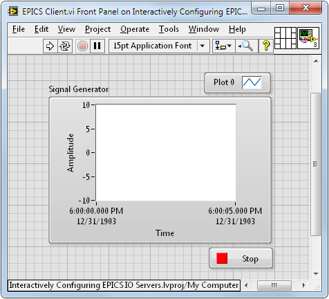
Figure 11: EPICS Client VI Front Panel
- Build the block diagram show in Figure 12
-
Add a While Loop and wire the Stop Button to the conditional terminal of the loop
-
Add the ClientAmplitude and ClientFrequency shared variables to the block diagram
-
Add a Basic Function Generator to the block diagram
-
Wire the ClientFrequency shared variable to the frequency input of the function generator
-
Wire the ClientAmplitude shared variable to the amplitude input of the function generator
-
Wire the Signal Out terminal of the Basic Function Generator to the waveform chart
-
Add a 100 ms Wait to the loop to give the processor time for other tasks
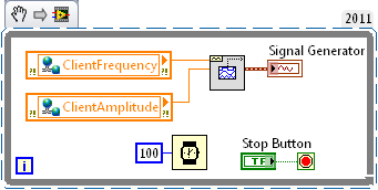
Figure 12: EPICS Client VI Block Diagram
Examining Flow of Communication
-
Run Server.vi, notice that Server Library.lvlib is automatically deployed
-
Run Client.vi, notice that Client Library.lvlib is automatically deployed
-
Make changes to the controls on the Server front panel, the client will update accordingly
-
See Figure 13 for a view of the front panels side by side
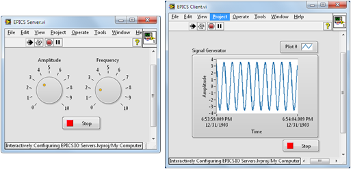
Figure 13: Server & Client Front Panels Running Simultaneously
- Open Distributed System Manager (DSM)
-
Select Tools » Distributed System Manager from the top menu of either VI
-
Browse to Localhost then select Client Library and Server Library to expand
-
The network published shared variables and process variables can now be viewed
-
Multiple items can be viewed simultaneously by holding Ctrl during selection
-
See Figure 14 for a view of DSM that shows all values being updated
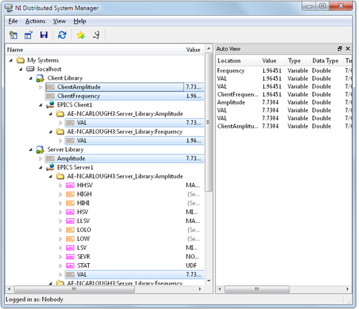
Figure 14: Viewing Flow of Communication in Distributed System Manger
Figure 14 shows the flow of communication as data passes between the EPICS Server and EPICS Client. The four steps in this process for each element are as follows:
-
LabVIEW Server VI writes to shared variables hosted on the server
-
EPICS Server I/O server updates values from shared variables to EPICS process variables
-
EPICS Client I/O Server reads values from EPICS process variables and writes to shared variables
-
LabVIEW Client VI reads from shared variables hosted on client