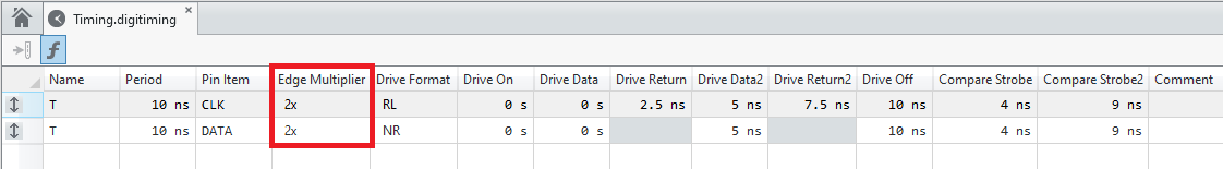
Beginning with Digital Pattern Editor 18.0 (DPE 18.0), the functionality of Edge Multiplier has been added. Therefore, Setting Edge Multiplier to 2X can achieve data rates higher than the default vector speed.
Edge Multiplier splits a vector period across multiple DUT cycles. First of all, in Timing, set Edge multiplier to
2X as shown below.
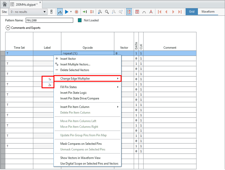
After that, If you set the
Change Edge Multiplier from
1X to
2X in the pattern file as shown below, you can use up to two pin states per vector.
Regardless of the pin's edge multiplier, each vector has only one Time set and Opcode and consumes only one vector's memory. (You must specify two pin states, one per DUT cycle, using a single vector period as shown below.)
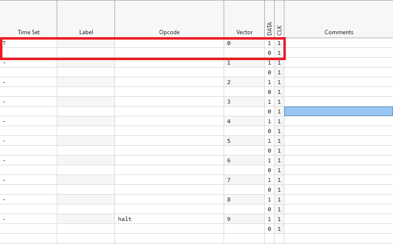
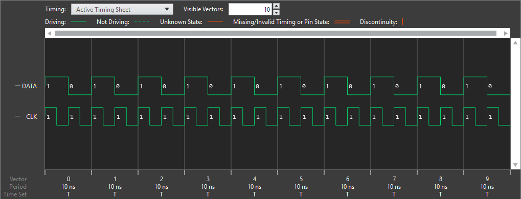
For example, if you set the edge multiplier to 2X in the 100 MHz Time Set, divide the 100 MHz period by 2 to have an effect of 200 MHz.
Additional Information
Refer to the
PXIe-6570 Specifications for details on Drive Format according to 2X for Edge Multiplier.