Required Software for the NI-9149
- LabVIEW 32-bit 2014 or later
- LabVIEW FPGA Module* 32-bit 2014 or later
- NI-RIO 14.0 or later
Note: Software should be installed in the order listed.
*LabVIEW FPGA is only necessary if you plan to write your own field-programmable gate array (FPGA) program for the FPGA target in the NI 9149. Use of the Scan Mode Interface is possible without the LabVIEW FPGA Module.
Required Software for the NI-9148
- LabVIEW 32-bit 2010 to 2019 SP1
- LabVIEW FPGA Module* 32-bit 2010 to 2019
- NI-RIO 3.5.1 or 19.6
Note: Software should be installed in the order listed.
*LabVIEW FPGA is only necessary if you plan to write your own FPGA program for the FPGA target in the NI 9148. Use of the Scan Mode Interface is possible without the LabVIEW FPGA Module.
Required Software for the NI-9147
- LabVIEW 32-bit 2014 SP1 or later
- LabVIEW FPGA Module* 32-bit 2014 SP1 or later
- NI-RIO 14.5 or later
Note: Software should be installed in the order listed.
*LabVIEW FPGA is only necessary if you plan to write your own field-programmable gate array (FPGA) program for the FPGA target in the NI 9147. Use of the Scan Mode Interface is possible without the LabVIEW FPGA Module.
Required Software for the NI-9146
- LabVIEW 32-bit 2011 to 2019 SP1
- LabVIEW FPGA Module* 32-bit 2011 to 2019
- NI-RIO 4.0 or 19.6
Note: Software should be installed in the order listed
*LabVIEW FPGA is only necessary if you plan to write your own FPGA program for the FPGA target in the NI 9146. Use of the Scan Mode Interface is possible without the LabVIEW FPGA Module.
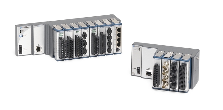
Setting Up the Hardware
In this section, we walk through the steps to set up the hardware for the NI 9149 Ethernet RIO expansion chassis. The steps detailed in this tutorial are the same for the NI 9148 Ethernet RIO expansion chassis, the NI 9147 Ethernet RIO expansion chassis, and the NI 9146 Ethernet RIO expansion chassis with the exception of the minimum software requirements detailed above.
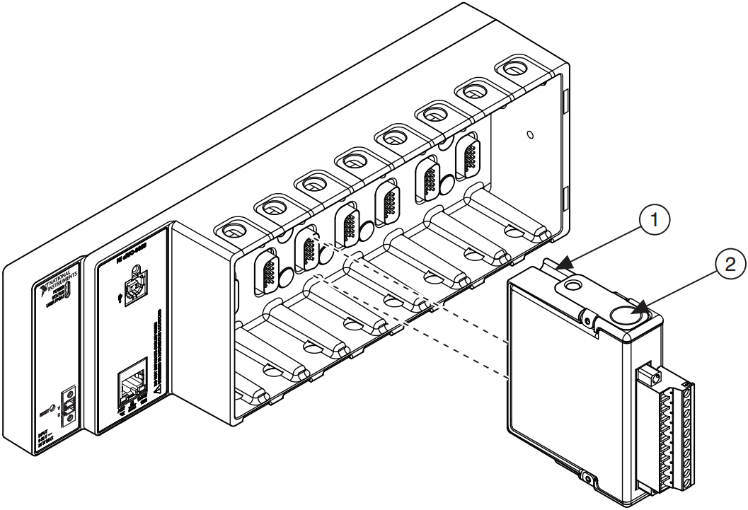
Installing C Series Modules
Complete the following steps to install a C Series I/O module in the chassis:
- Make sure that no I/O side power is connected to the module. Due to the hot-swappable ability of the C Series module, if the system is in a nonhazardous location, the chassis power can be on when you install modules.
- Align the C Series module with a module slot in the chassis as shown in the figure below. The module slots are labeled 1 to 8, left to right.
- Squeeze the latches and insert the module into the module slot.
- Press firmly on the connector side of the C Series module until the latches lock the module into place.
- Repeat these steps to install additional I/O modules.
Connecting Ethernet and Power
Ethernet RIO systems use Ethernet for all communication and configuration back to the development or host PC. To connect to an Ethernet network (hub or router), use a standard Category (CAT-5) or better shielded, twisted-pair Ethernet cable, or use an Ethernet crossover cable to connect the chassis directly to your development computer. For the NI 9149 and NI 9147, you can use the USB device port to connect the chassis to your PC instead of an Ethernet cable.
You can use the Ethernet port for different types of setup:
- Connect the expansion chassis is intended to be connected to your network using e.g. an Ethernet switch. This way, you can access the chassis from all devices connected to the network.
- Connect the expansion chassis directly to your PC's Ethernet port. You will only be able to access the chassis from your PC.
- Connect the expansion chassis to a Secondary Ethernet port of a cRIO. This way only the cRIO itself will be able to connect to the Expansion Chassis. This setup is not the intended use case for Ethernet RIO expansion chassis.
Before wiring power, ensure that your dip switches are in the OFF position (NI 9148 only). All dip switches should be in the OFF position when the chassis is shipped from NI.
- Ensure the power supply is not energized (in other words, not plugged into a power source) before connecting any wires.
- Remove the COMBICON power connector from the front of your Ethernet RIO chassis by loosening the two captive screws that hold it in place.
- Connect the positive lead of the power supply to the V terminal (NI 9149, 9147, and 9146) or to the V1 or V2 terminal (NI 9148), and the negative lead to one of the C terminals on the power connector that was shipped with your Ethernet RIO chassis. Tighten the leads in the connector by turning the captive screws on the side of the connector and ensure the wires are snugly in place.
- Reattach the COMBICON connector to your Ethernet RIO chassis.
Configuring Your Hardware
- Disable secondary network interfaces, such as the wireless access card on a laptop. For initial setup, NI software searches for your NI CompactRIO system through the primary network interface on your computer. Disabling all additional network interfaces ensures that your CompactRIO system is easy to find on the network.
- Open Measurement & Automation Explorer (MAX) by going to Start»All Programs»National Instruments»Measurement & Automation and expand Remote Systems. You should see your Ethernet RIO system in the list. By default, your reconfigurable I/O (RIO) system will either acquire a network address via DHCP if it is supported on your network, or if you are connected directly to your PC via a cross over cable, it will assign a link-local address.
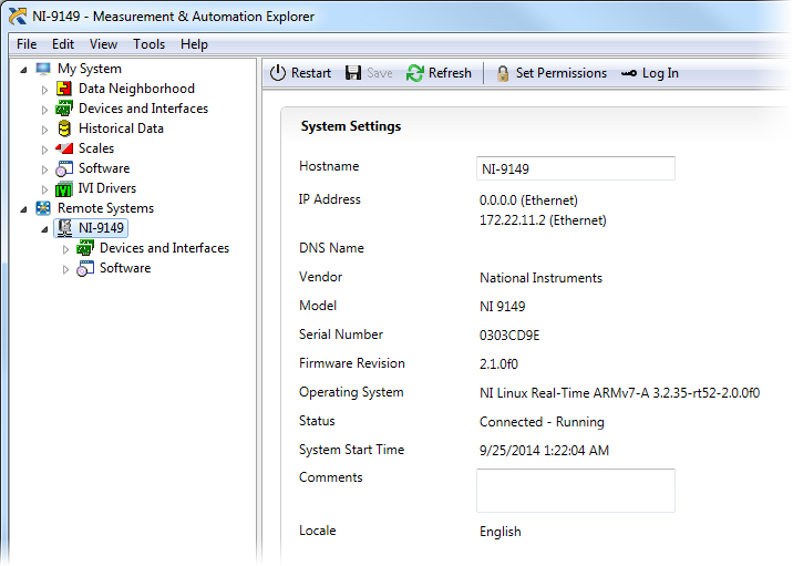
If you do not see your system, follow the steps outlined in the document titled NI CompactRIO or Network Device Doesn't Show Up or is Missing in MAX .
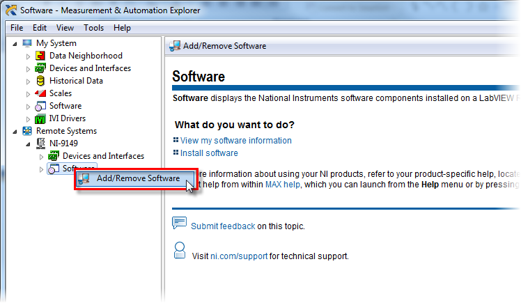
Installing Software on Your Ethernet RIO Expansion Chassis
Your Ethernet RIO chassis should be configured with a valid IP address and the correct software should be installed on your development computer by this point. The status light on your Ethernet RIO chassis should be repeatedly blinking twice. This indicates that a valid IP address is assigned, but there is no software installed on the controller.
- Expand the Ethernet RIO item under Remote Systems, right-click on the Software item, and select Add/Remove Software.
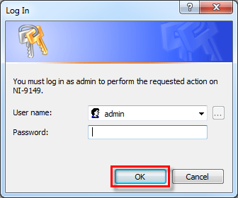
- For the NI 9149, you must log into the device to install the software. Use the default user name and password combination to log in: username - admin, password - <blank>.
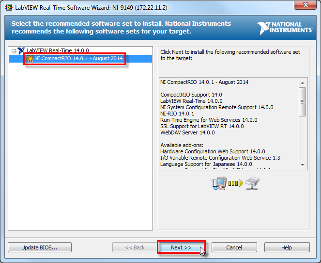
- Select the most recent NI-RIO Recommended Software Set (RSS) and click Next. Continue clicking Next until the software install wizard begins installing software on the controller. The process of installing software can take a few minutes, so feel free to go grab a cup of coffee or check your email while the wizard completes the install process.
- Once the software installation process has completed, click the Finish button and close MAX. Your Ethernet RIO system will now reboot. After it has finished rebooting, your system is ready to program and use.
Programming Your Ethernet RIO Expansion Chassis
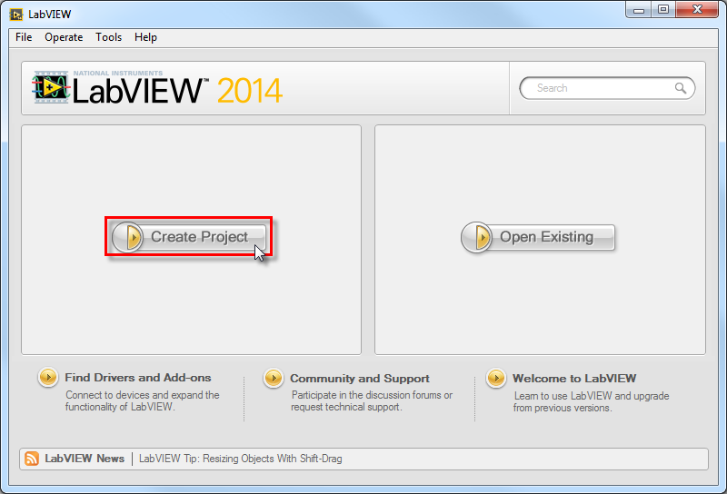
- Start by opening LabVIEW and clicking Create Project in the LabVIEW Getting Started screen. Then select Blank Project in the Create Project window.
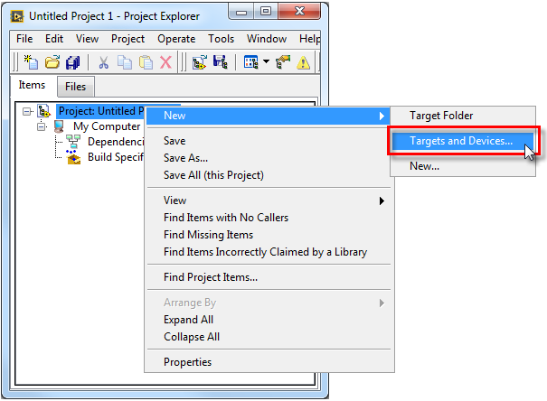
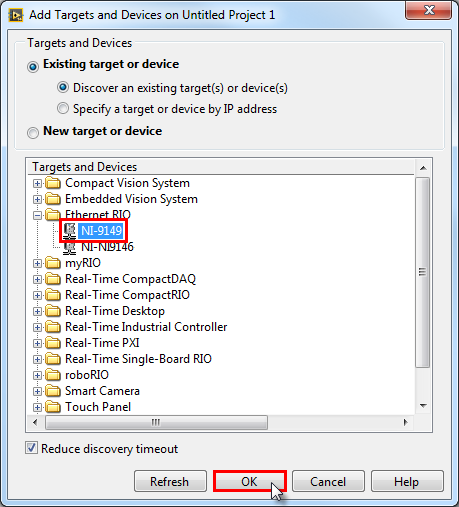
- Right-click the Target in the project tree and select New»Targets and Devices…
- Double-click on the Ethernet RIO folder, select your chassis, and click OK.
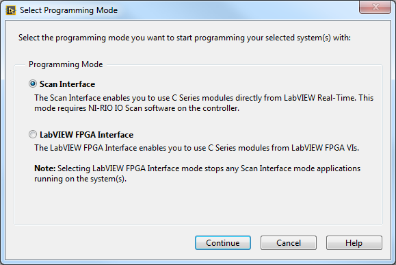
- The next window asks you to select your programming mode. If you have the LabVIEW FPGA Module, you have the option to use the LabVIEW FPGA Interface. This is the more powerful and flexible way to interface with your RIO hardware. However, without the LabVIEW FPGA Module you can use the Scan Interface Mode. Click on the mode you want to use and click Continue.
Continue to the programming with the Scan Interface section of this tutorial.
Continue to the programming with FPGA Mode section of this tutorial.
- Your Ethernet RIO chassis is now added to the project. Expand the Ethernet RIO item and the chassis item in the project tree to see your available modules. Expand a module item to see the available I/O channels. Your project should now look similar to the image below.
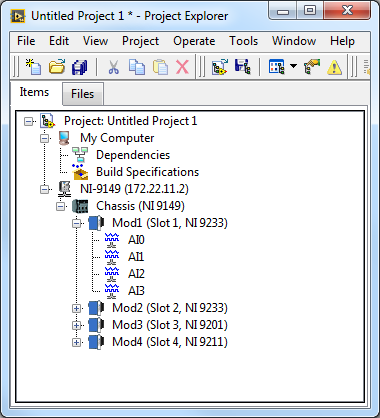
- Click Save and save your project in a location where you can find it again.
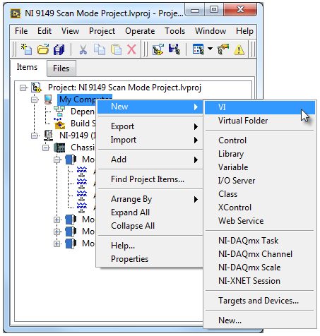
Now you will create a simple LabVIEW program referred to as a VI, or virtual instrument, that will access the Ethernet RIO I/O across the network from your Windows machine. - Right-click My Computer in the project tree and select New»VI to add a new VI to your project.
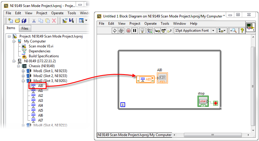
- Navigate to the block diagram and add a While Loop from the functions palette. Then drag and drop an I/O Scan Variable from the project tree into the While Loop. Create an indicator for your I/O variable and ensure that a Stop control is wired to the loop condition. Your block diagram should look similar to the image below.
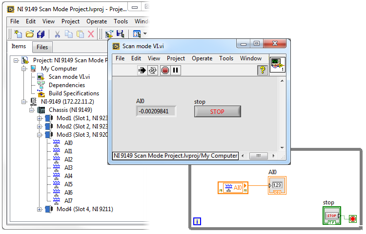
- Save your VI and click the Run Arrow from your front panel. You are now accessing I/O from your NI 9149 chassis across the network from your development PC using the Scan Mode Interface.
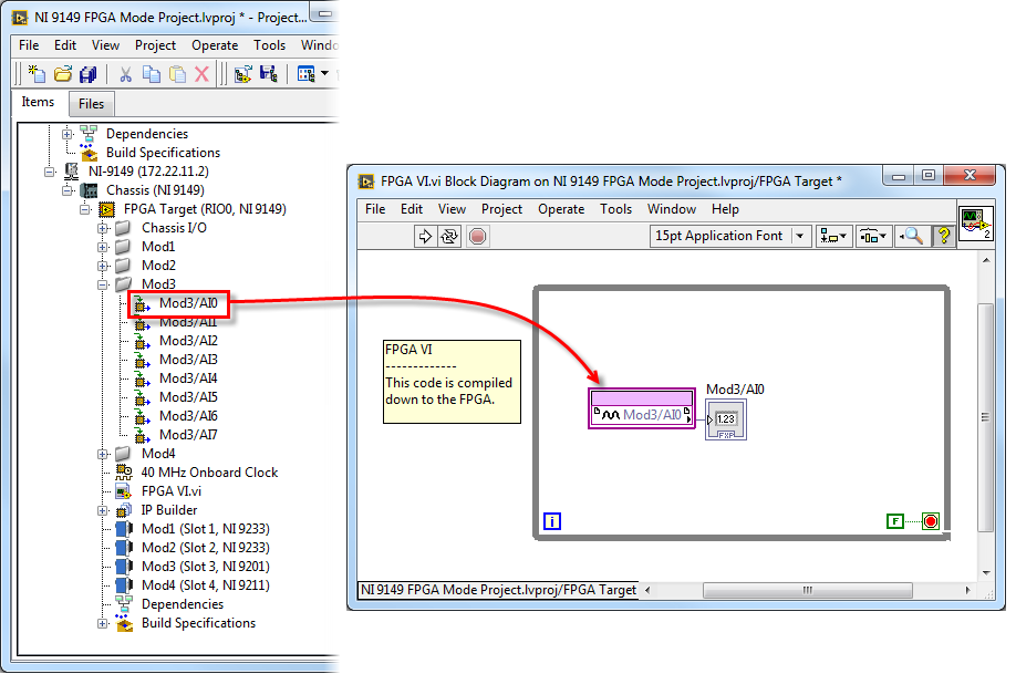
- Your Ethernet RIO chassis is now added to the project. Expand the Ethernet RIO item, the chassis item, and the FPGA Target in the project tree to see your available modules. Expand a module item to see the available I/O channels. Your project should now look similar to the image below.
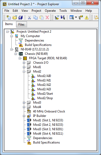
- Click Save and save your project in a location where you can find it again.
Now you will create a LabVIEW FPGA VI that will be compiled to the FPGA target on your Ethernet RIO. From there, you will create a Host VI that will run on the PC and communicate with the FPGA VI on the Ethernet RIO FPGA Target.
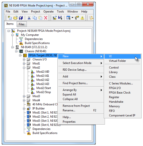
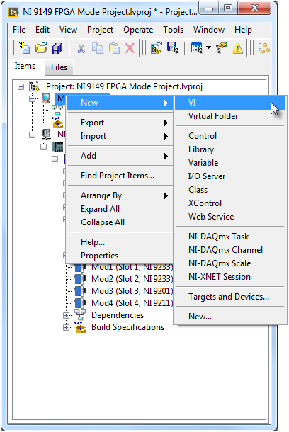
- Right-click the FPGA Target in the project tree and select New»VI to add a new FPGA VI to your project.
- Navigate to the block diagram and add a While Loop from the functions palette. Then drag and drop an I/O Node from the project tree into the While Loop. Create an indicator for your I/O Node and ensure that a False constant is wired to the loop condition. Your block diagram should look similar to the image below.
- Save your VI and click the Run arrow from your front panel. This launches the FPGA Compiler, which compiles your FPGA VI for the FPGA Target.
- While the FPGA VI is compiling, we can work on the Host VI. Right-click My Computer in the project tree and select New»VI to add a new Host VI to your project.
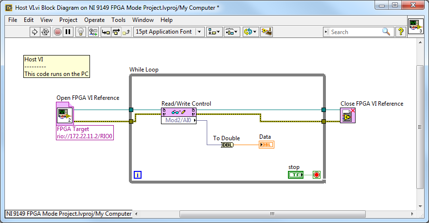
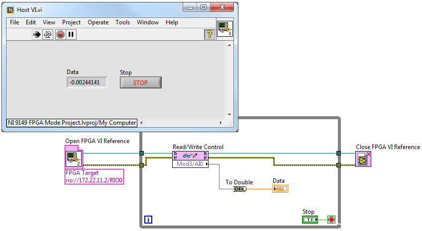
- Navigate to the block diagram and add a While Loop from the functions palette. Then add the Open FPGA VI Reference, Read/Write Control, and Close FPGA VI Reference functions into the While Loop and wire them as seen in the image below.
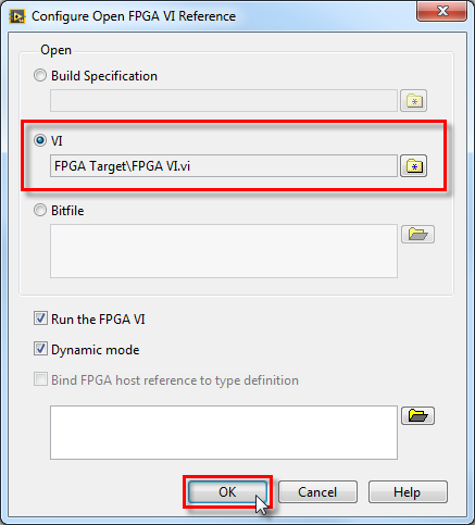
- Right-click on the Open FPGA VI Reference and select Configure Open FPGA VI Reference. Select the VI radio button and browse to your FPGA VI. This points your Host VI to your FPGA VI that is running on the FPGA Target.
- Save your VI and click the Run arrow from on the front panel of your Host VI. You are now accessing I/O from your Ethernet RIO chassis across the network from your development PC using FPGA programming.
Note: When referencing an Ethernet RIO Expansion Chassis FPGA VI from another RIO target's RT VI, you will need to specify the Ethernet RIO Expansion Chassis resource name in the Open FPGA VI Reference. The resource name will be a constant value of the format: rio://<xxx.xxx.xx.xx>/RIOX