RS-485 is set up for four-wire communication by default. To connect a 2-wire device, you will need to short the transmit and receive signals together on the RS-485 port. Note that this is necessary to connect RJ45 (8-pin modular jack) ports to RJ50 (10-pin modular jack) ports. Follow the instructions below.
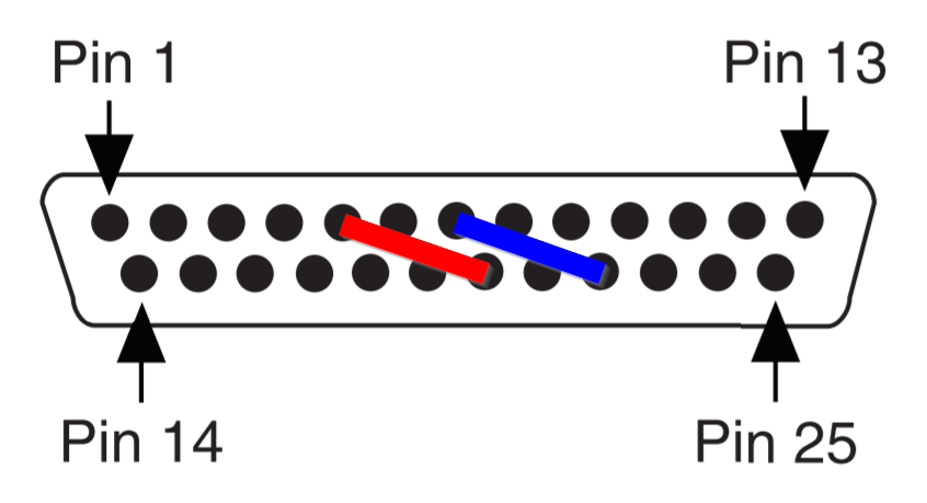
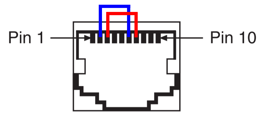
- On the RS-485 connector, place jumper wires between TXD+ and RXD+, and between TXD- and RXD-. Refer to the pins below based on your connector type.
| Connector | Pins | Diagram |
| DB-9 | Pin 8 and Pin 4 (TXD+ and RXD+)
Pin 9 and Pin 5 (TXD- and RXD-)
|  |
| DB-25 | Pin 5 and Pin 20 (TXD+ and RXD+)
Pin 22 and Pin 7 (TXD-and RXD-)
|  |
| RJ-50 | Pin 3 and Pin 7 (TXD+ and RXD+)
Pin 2 and Pin 6 (TXD- and RXD-)
|  |
- Wire the 2-wire device's send pin (TXD) to both TXD- and RXD-. Wire the device’s receive pin (RXD) to both TXD+ and RXD+. Consult your device’s user manual for reference.
- Configure the COM port to communicate in 2-wire Auto mode by referring to Setting the Transceiver Wire Mode of Ports on National Instruments Serial Boards.
- Test communication with VISA Interactive Control. Refer to your device’s user manual for a supported command.
Please be aware that NI's serial cards do not support terminating resistors for 2-wire communication lines. If you need to terminate the communication line on the board's side, you will need to create a custom cable.