Introduction
The new schematic capture net system in NI Multisim provides a number of benefits to the user. Most notably engineers can take advantage of an up-to-date and intuitive circuit design environment. As a part of the complete re-architecture to our schematic capture environment in Multisim 11, users can now place a host of different connectors to symbolize the virtual connections in their designs.
New on-page and global connectors are now available. By using these new features you will instantly be able to:
- Improve your approach to drawing schematics with clearer indication of net connections
- Make circuit files more stable (less likely to be corrupted)
- Avoid unnecessary errors made by improper wiring and forgotten connections
- Quickly get started with a design, regardless of the last time you had worked with it
- Communicate schematics and design decisions to management easier
By reading this tutorial you will learn more about on-page and global connectors, when and how to use them, and finally how to transition from using our legacy schematic capture environment.
Glossary
Connectors allow you to show connections on a schematic without having an actual wire drawn between two objects. The connector indicates to the viewer that a specific wire is connected to another wire in the circuit. By using such connectors you can clear up a design and avoid spaghetti wiring and poor naming conventions (hallmarks of an ineffective schematic).
You can access these connectors by going to Place >> Connectors (Figure 1). You will notice that there are two options here of note; "On-Page Connector" and "Global Connector".
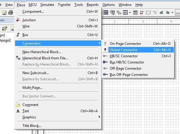
Figure 1 - Place a Connector
On-Page Connectors
An on-page connector shows a connection on a single schematic page. If you have two wires that you would like to have connected together on one page of your design then you can use a on-page connector. In figure 2 below you will see that the oscilloscope and output of the circuit are connected together through the on-page connector named "Output".
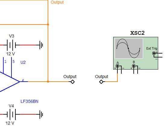
Figure 2 - On-Page Connectors
Global Connectors
A global connector, similar to an on-page connector creates a connection between various wires. However a global connector is not limited to a single schematic page. A global connector can be used to create connections through hierarchy (sub-circuits, hierarchical blocks and multiple-pages).
Benefits of Using Connectors
In the past when creating a connection between two separate wires you would create a virtual connection symbolized by a "hanging junction". The only way one could properly ascertain that the wire is connected to another wire is through the net-name. This can be cumbersome, and from a visual perspective can be difficult to view.
Considering that schematics must often be viewed by others (colleagues, management etc...) a design diagram that is difficult to read can cause confusion.
Poor wiring can cause mistakes. Often engineers will inadvertently make a connection between wires and components that make their designs function erroneously. As such the legacy method of virtual connections can be prone to mistakes.
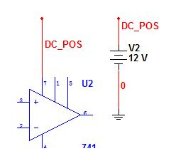
Figure 3 - Legacy Connections
With the new on-page and global connectors these issues can be overcome. Engineers can now very clearly identify a connection between nets as seen in previous examples in this tutorial. Design decisions can be very clearly communicated through all of these various tools whether to fellow engineers or management.
An important by-product of all of these changes is that design errors caused by potential wiring mistakes are minimized. Poor wiring and improper connections are removed from the design flow, and a best practices approach is achieved.
Transitioning Old Designs to the New Schematic Capture System
The new schematic capture net system (onpage and global connectors, new bus labels, net net naming) facilitates far more solid and stable designs. Circuit files are less likely to be corrupted, and designers are less likely to overlook virtual connections (thereby inadvertently short-circuiting nets).
However, to permit such a significant new feature NI did need to re-architect Multisim. This does mean that the "old" net system and legacy design approaches have been made obsolete. When converting or upgrading old designs into Multisim 11 your circuit file will take on the characteristics of the "new" system.
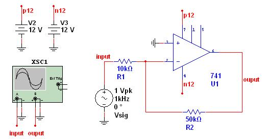
Figure 4a - Multisim 10.x File
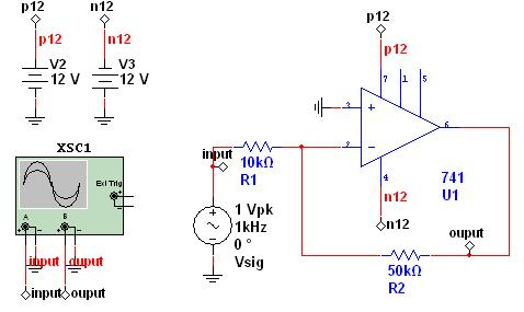
Figure 4b - Conversion of Multisim 10.x File to Multisim 11.0
This conversion process of old designs does mean that old virtual connections, hierarchical blocks, subcircuits, and buses, will be visually changed. Virtual connections will be replaced by connectors, new labels will be added to buses and nets within blocks will now have a unique net name across the project. If your designs make use of these aforementioned features, you will need to perform a one-time review of your design to ensure the automatically placed connectors are not overlapping objects (such as other wires and connectors).
This one-time review is highly recommended and necessary for a smooth transition to those that migrate old designs to Multisim 11. Though this may take time initially we strongly encourage you to do so in order to benefit from all the new features of Multisim 11 (including Forward and Backwards Annotation). The time it will take is dependent on your project and how heavily you have used virtual connections, blocks and buses.