Software Installation
In order to perform real-time testing with VeriStand, you will install software on your Windows PC and your real-time target. Follow the steps below to install the necessary software on both computers.
Host PC Software Installation
-
Install VeriStand and its associated drivers in accordance with the Getting Started With VeriStand tutorial. In addition to the required drivers, install the XNET driver from the optional drivers list.
-
Install the latest version of the ECU Measurement and Calibration Toolkit. You can download this on the ECU Measurement and Calibration Toolkit download page.
Note: Make sure the corresponding VeriStand 20XX Support version option is selected when installing the ECU Measurement and Calibration Toolkit.
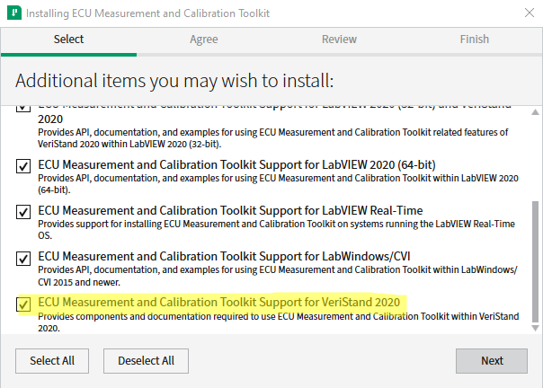
Figure 1. Install VeriStand support for the ECU Measurement and Calibration Toolkit
Software Installation on the Real-Time Target
Install software on the real-time target computer in accordance with the Getting Started With VeriStand tutorial.
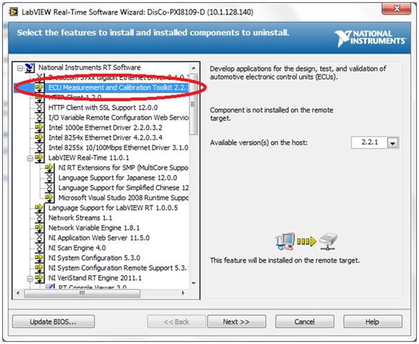
Figure 2. Install the ECU Measurement and Calibration Toolkit on the Real-Time target
In addition, choose to install the ECU Measurement and Calibration Toolkit. This installs the necessary files to use the XCP or CCP Master custom device on VeriStand.
VeriStand Project Setup
Configure your first VeriStand project by following the instructions in Section 5 of the Getting Started With VeriStand tutorial.
Configuring the XCP/CCP Master
With the System Explorer open, you can add XCP or CCP Master functionality to the System Definition by navigating the System Explorer tree to Targets » Controller » Custom Devices and right-clicking on Custom Devices » National Instruments » XCP or CCP Master.
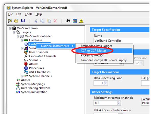
Figure 3. Add the XCP or CCP Master
After adding the XCP or CCP Master, select it in the System Explorer tree and configure the calibration settings for your application. The items below describe the menu options for the XCP/CCP master custom device and how to configure your System Definition to perform calibration.
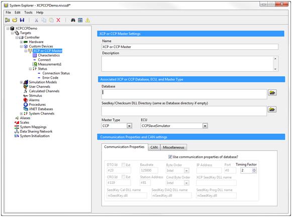
Figure 4. XCP or CCP Master settings page.
XCP or CCP Master Settings - Sets the name and description of the Master device.
Associated XCP or CCP Database, ECU, and Master Type –
Database – Database file used for calibration. You can select an ECU device database file in ASAM, MCD, or 2MC (.A2L) format.
Seedkey/Checksum DLL – A Dynamic Link Library that implements a function to calculate a key to a given seed to unlock access to ECU resources. This property determines the directory where the custom device expects to find the Seedkey or Checksum DLL. If the property is an empty string (default), the custom device expects the DLLs in the same directory as the A2L file. If your DLLs are in a different directory, set this property pointing to this directory.
Master Type - The Master device (host) is the calibration/monitoring tool for initiating data transfers on the bus by sending commands to slave devices. The Master can be set to CCP, XCP on CAN, XCP on TCP, or XCP on UDP protocols.
ECU – Defined in the Database file, the ECU type field will auto-populate when the Database is selected with the programmed devices.
Communications Properties tab
Use communication properties of database? - Sets various properties for either CCP/XCP with CAN or XCP with TCP/UDP. If the Communication Properties are not stored in the ASAM MCD 2MC file, the communication properties must be manually set.
DTO Id – Sets the DTO ID (Data Transmission Object) which is used by the ECU to respond to commands and send data and status information to the Master.
Ext – Use extended CAN Identifier (29 bit) for DTO.
CRO Id – Sets the CRO ID (Command Receive Object) which is used to send commands and data from the host to the slave device.
Ext - Use extended CAN Identifier (29 bit) for CRO.
Baudrate - Sets the Baud Rate in use by the NI-CAN Interface. Basic baud rates such as 125000 and 500000 are specified as the numeric rate. Advanced baud rates are specified as 8000XXYY hex, where YY is the value of Bit Timing Register 0 (BTR0), and XX is the value of Bit Timing Register 1 (BTR1) of the CAN controller chip.
Station Address - Sets the Station Address of the slave device. CCP is based on the idea that several ECUs can share the same CAN Arbitration IDs for CCP communication. To avoid communication conflicts, CCP defines a Station Address that has to be unique for all ECUs sharing the same CAN Arbitration IDs. Unless an ECU has been addressed by its Station Address, the ECU must not react to CCP commands sent by the CCP master.
Byte Order - Sets the Byte Order of the CCP/XCP slave device.
0 - Intel format: Bytes are in little-endian order, with least-significant bit first.
1 - Motorola format: Bytes are in big-endian order, with most-significant bit first.
Cmd Byte Order - Sets the Byte Order of the CCP or XCP commands.
0 - MSB_LAST: The CCP slave device uses the MSB_LAST (Intel) byte ordering.
1 - MSB_FIRST: The CCP slave device uses the MSB_FIRST (Motorola) byte ordering.
IP Address - Sets the IP address of the slave device. A slave device connected by Ethernet and TCP/IP or UDP/IP protocol is addressed by its IP Address and Port number.
Port - Sets the IP Port number of the slave device. A slave device connected by Ethernet and TCP/IP or UDP/IP protocol is addressed by its IP Address and Port number.
Timing Factor - Sets the timing factor to increase the XCP or CCP Command timeouts by this value. For details on the default Command Timeout values, refer to the CCP or XCP Protocol Specification.
XCP SeedKey DLL name - Sets the file name of the XCP SeedKey DLL.
SeedKey Cal DLL name - Sets the file name of the SeedKey DLL used for Calibration purposes.
SeedKey DAQ DLL name - Sets the file name of the SeedKey DLL used for DAQ purposes.
SeedKey Prog DLL name - Sets the file name of the SeedKey DLL used for programming purposes.
CAN tab
Select CAN interface – Sets the NI-XNET or NI-CAN CAN interface name.
NI-XNET? - Specifies if the CAN interface is an XNET module.
NI-XNET Bus Termination – Activates the CAN bus termination on the NI-XNET card. For all XNET devices, the termination is software selectable. XNET provides the option of 80 Ohms between Bus Plus and Bus Minus or no termination. The Termination property configures the onboard termination of the NI-XNET interface CAN or LIN connector (port). The Boolean property supports two values: TRUE = Termination ON and FALSE = Termination Off. However, different CAN or LIN hardware has different termination requirements, and the termination values have different meanings. Refer to the Termination attribute in the XNET API for more details. (This property is supported for NI-XNET devices only.)
CAN Bitfile – Selects the C Series module bitfile type for CompactRIO use (NI 985x or NI 986x)
RIO Device – Selects the RIO resource your C Series modules resides in.
Bitfile Path – Selects the location of the bitfile.
Miscellaneous
Custom Device Host Communication Port – IP Port number the Custom Device Host will use to communicate. Must be different for each instance.
Value change tolerance- Minimum change of item value before ECU is written.
Delay Before Reconnect – If communications error occurs, the custom device waits this time before re-establishing the communication.
CCP Single Byte DAQ List - Sets the ECU to support single-byte or multi-byte DAQ list entries.
Characteristics
ECU Characteristics are maps of the ECU internal variables, which may be used as calibration information or set-point information. The ECU memory content of Characteristics can be read or even changed with the help of the ECU Measurement & Calibration Toolkit.
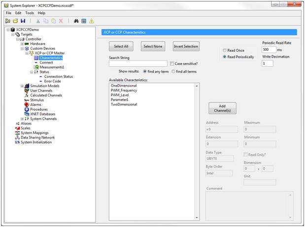
Figure 5. – Characteristics Configuration Page
Available Characteristics: List of available channels to add to the Master.
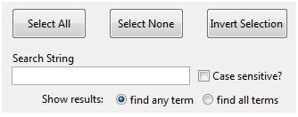
Searching: User interface to facilitate navigation through channels defined in the database.
Select All – Selects all the channels in the Available Characteristics Listbox.
Select None – De-selects all the channels in the Available Characterstics Listbox.
Invert Selection - Inverts channel selection in the Available Characterstics Listbox.
Search String – Searches all channels which match string input.
Case sensitive? – Search results are filtered to match letter case.
Show results – When search string has multiple terms, you can select if the search terms are mutually exclusive or not.
Read Parameters
-
Read Once – Characteristics are read only at start, assumed to be changed by the master only.
-
Read Periodically – Characteristics are read periodically, assumed to be changed by the slave.
-
Periodic Read Rate – Set the rate NI VeriStand will read values from the ECU.
-
Write Decimation – Use the decimation control to slow updates sent to the ECU. New values are sent to the ECU. Setting decimation can prevent flooding on rapidly changing data.
Adding Channels
-
Add Channels(s) – Adds the selected channel from the Available Characteristics Listbox to the Characteristics list.
-
Address - Memory address of the characteristic within the ECU.
-
Extension – Address extension.
-
Maximum – Maximum value of a characteristic element.
-
Minimum – Minimum value of a characteristic element.
-
Data Type – Displays the associated data type of the characteristic element.
-
Read Only? – Characteristic cannot be written to ECU.
-
Byte Order – Displays the associated Byte Order of the characteristic element.
-
Dimension – Size of the characteristic.
-
Unit – Units of characteristic values
-
Comment – ECU description of the characteristic.
Measurements
The ECU Measurement & Calibration Toolkit provides the user access to ECU internal physical values defined by their names in the ASAM MCD 2MC database file. Based on this information, the ECU M&C Toolkit communicates through CCP or XCP to the ECU. A DAQ (data acquisition) list can be set up, which sends ECU internal data synchronously or asynchronously to the CCP or XCP master. The CCP/XCP Master provides a way to configure several Measurement channels into a single Measurement task. A common use of a task is to read DAQ channels available on the ECU.
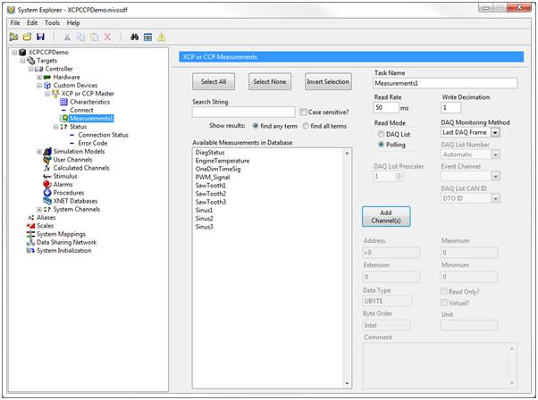
Figure 6. Measurements Settings Page
Available Measurements in Database – List of measurements defined in the database.
Task Name – Name of the Measurements Task.
Read Rate - Set the rate NI VeriStand will read values from the ECU.
Write Decimation – Use the decimation control to slow updates sent to the ECU. New values are sent to the ECU. Setting decimation can prevent flooding on rapidly changing data.
Polling – The master sends requests for every single measurement value. Polling is typically more CPU intensive but is useful when variable values are needed at a particular time.
DAQ List – DAQ List define a list of parameters that are periodically transmitted from the ECU at a specified rate. On average, DAQ Lists uses less CAN traffic. When using multiple DAQ Lists, they can transmit at different rates allowing flexibility in optimizing total amount of traffic while achieving required sampling rates.
DAQ Monitoring Method
-
Last DAQ Frame – Verifies that ECU is still performing DAQ by the time since the last DAQ frame.
-
Session Status – Retrieves the current session status from the ECU to verify if ECU is still performing DAQ.
-
None
DAQ List Number – Automatic or predefined DAQ List Number
DAQ List Prescaler – Reduces DAQ List data rate sent by the ECU by a factor.
Event Channel – Determines the sending rate of DAQ messages by the ECU. Available channels can depend on the DAQ List number.
DAQ List CAN ID – Can depend on the DAQ List number. DTO ID is specified on the main page of the XCP or CPP Master Device.
Address - Memory address of the characteristic within the ECU.
Extension - Address extension.
Maximum - Maximum value of a characteristic element.
Minimum - Minimum value of a characteristic element.
Data Type - Displays the associated data type of the characteristic element.
Read Only? - Characteristic cannot be written to ECU.
Virtual? – Returns whether the Measurement is virtual. Virtual Measurements are not transmitted by the ECU but are calculated in the application. They return an error when opened in a DAQ list.
Byte Order - Displays the associated Byte Order of the characteristic element.
Unit - Units of characteristic values
Comment - ECU description of the characteristic.
Adding Measurement and Characteristics
To begin adding measurements in your System configuration, select the Characteristics page and choose which channels to add:
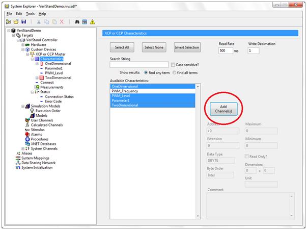
Figure 7. Add Characteristics to the Master
As Channels are added, they will start populating the Characteristics field in the System Explorer tree. When finished adding the Channels, save and exit from the System Explorer.
Using Workspace Controls
Now that Channel set-up is complete, deploy your System Definition File. From the Project Explorer, deploy your System Definition File by following the instructions on the section Deploying VeriStand Projects in the Getting Started With VeriStand tutorial. Once your System Definition file deploys successfully, you can start customizing your Workspace. VeriStand allows you to add/remove/edit Workspace controls and indicators as your System Definition File executes on the target. The VeriStand Workspace must be in Edit Mode in order to add controls (Screen >> Edit Mode).
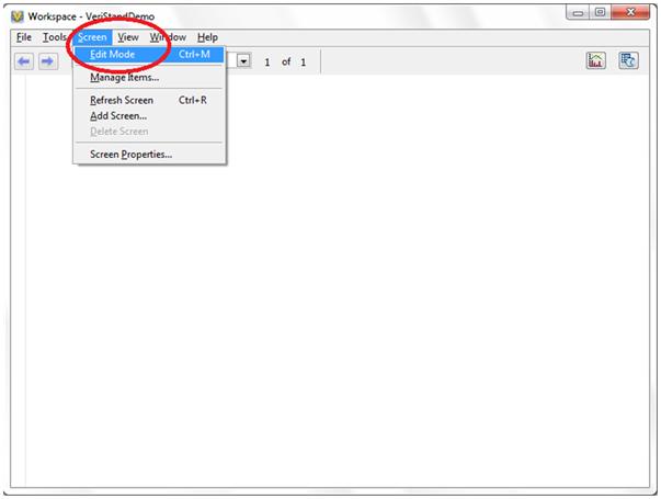
Figure 8. Switch Workspace to Edit Mode to add/remote/edit Controls and Indicators
Four workspace controls are bundled with the add-on to facilitate easy viewing and editing of characteristic curves and fields, as well as query characteristic and measurement data from the ECU that has not been added to the system configuration.
The four controls are:
-
Single Characteristic
-
Single Measurement
-
Field Control
-
Curve Control
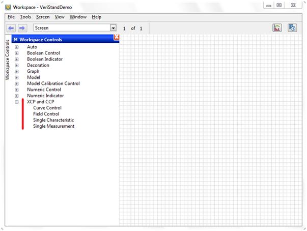
Figure 9. XCP and CCP Controls and Indicators
To insert a control, simply drag and drop the control name to the Workspace grid, a dialog asks the user to select an available characteristic or measurement. This list is populated by either looking on disk for the database file used with the system, or by querying the running custom device. This allows the controls to be setup while the system is offline, and for host systems to connect to the running target and setup a workspace without having the database file.
Write
Data is never written to the ECU unless a new and different value is provided for a characteristic or measurement either through a channel, the workspace controls, or the add-on's API. This means no writes ever happen until a value changes. Users are then in total control of the write traffic on the bus. The measurements and characteristics pages have a write decimation control to configure decimation for writes from channel data. This enables bus load management on continuously changing input data.
Characteristic Read
Characteristic data is queried from the ECU, and then the ECU responds with the data at the rate of the "Read Rate" control on the characteristics page. To minimize this traffic, only add characteristics you are interested in to your system configuration rather than the entire database. Use the API and workspace controls to see other data.
Measurement Read
DAQ List Setting
The event channels defined in the A2L file are loaded into a drop down control, allowing the user to select the event channel in the A2L file they would like their measurement communication to use. The host (VeriStand) will tell the ECU to use this event channel and the ECU will send data to the host at the rate that event channel defines. This effectively halves your bus traffic as the host no longer has to ask the ECU to send data.
Polling Setting
Measurement data is queried from the ECU, and then the ECU responds with the data at the rate of the "Read Rate" control on the measurements page. To minimize this traffic, only add measurements you are interested in to your system configuration rather than the entire database. Use the API and workspace controls to see other data.
To plot a measurement, select a Simple graph by browsing to Graph >> click and drag Simple to the workspace.
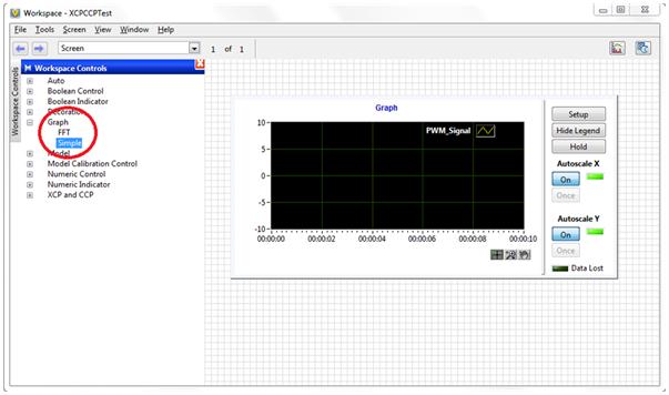
Figure 10. Add Simple Graph to the Workspace.
Once the graph is dropped in the Workspace, select the measurement channels to be displayed. For now, the PWM_Signal can be chosen to be plotted.
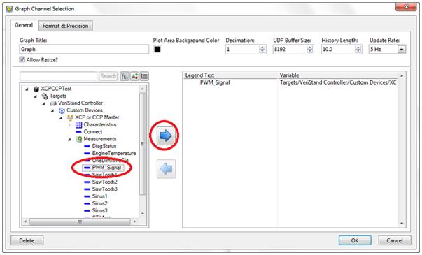
Figure 11. Select ECU Measurement Channel to be displayed on Graph.
Once you have selected the PWM_Signal, the graph will automatically begin to update you’re your data.
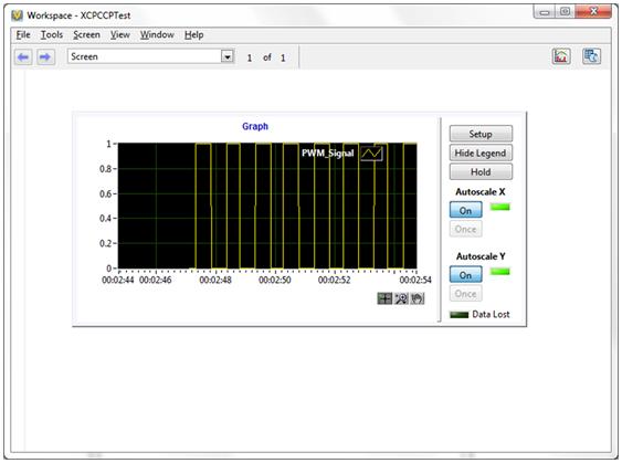
Figure 12. ECU Measurement Channel displayed
API
An API is provided with the add-on to query characteristic and measurement information directly from the running custom device. This is useful for getting characteristic and measurement properties, as well as data values if the item has not been added to the system definition. This API can be used from other environments like TestStand or LabVIEW.
The function calls provided include:
-
Get and Set Characteristic Data (Single, Curve (1d), and Field (2d))
-
Get and Set Measurement Data
-
Get Item Properties
-
Get Item Type Names
Using the get and set data calls, you can calibrate the ECU under test. Get Item Properties allows you to retrieve valuable information like read-only status, scaling information, address, etc. Get Item Type Names will return lists of available items from the ECU under test.
Managing Bus Load
Managing bus load is important for a deterministic CAN system. Understanding the read and write behavior of this custom device will foster better bus load management.
Bus traffic is something that can be managed in many different ways. The number one way to manage bus traffic with this add-on is to only add characteristics and measurements to the system configuration that you must interact with from the VeriStand engine. An example of needed interaction would be from an alarm or stimulus profile. Characteristics or measurements that do not need this interaction should not be added to the system configuration. They can be queried and written to from the workspace or API without having to be in the system configuration. For more information related to this, see the appropriate sections in this document.
Many users have a dedicated set of CAN lines for XCP/CCP, which is the best route to manage bus load. A single NI-XNET card would be useful here, with one port for XCP/CCP and the other for other CAN communication.
XCP/CCP CAN communication can also be given a high arbitration ID thus giving it a low priority. More important messages will then supersede XCP/CCP traffic.
Debugging Tools
The ECU Measurement & Calibration Toolkit includes an A2L database viewer and a CCP/XCP monitor which can be used for debugging. The ECU MC A2L Viewer can be used to view configuration information of existing A2L databases with an organized user interface.
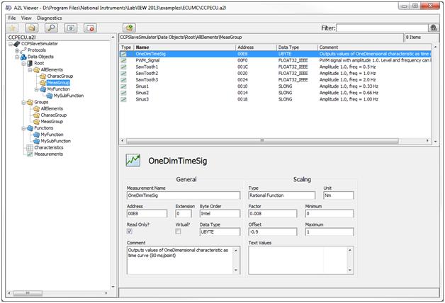
Figure 13. A2L Viewer
In addition, the ECU Measurement & Calibration toolkit includes the CCP/XCP spy monitoring tool. Launch this tool from Start menu >> Program >> National Instruments >> ECU Measurement and Calibration Toolkit >> CCP and XCP Spy.
CCP/XCP-Spy is an application that monitors, records, and displays CCP and XCP communication commands and parameters called by your ECU M&C application using the CCP or XCP protocol. Use CCP/XCP-Spy to analyze your application's communication and to verify that the communication with your ECU slave is correct.

Figure 14. CCP/XCP Spy.
CCP/XCP-Spy may slow down the performance of your application, communication to your ECU slave, and the entire system. You should use CCP/XCP-Spy only while you are debugging or when performance is not critical.
You can use this application on Windows only when the ECU M&C master also is running on Windows.
Optional: Setting up an XCP/CCP Master and Simulated LabVIEW ECU Slave
The ECU Calibration and Measurement toolkit includes a simulated CCP and XCP slave ECU for LabVIEW. These simulated devices can be found in the NI Example Finder. Open the NI Example Finder by starting up LabVIEW and browsing to Help >> Find Examples… >> from the folders browse to Toolkits and Modules >> ECU Measurement and Calibration >> Demo ECUs >> select either CCP or XCP depending on your Master type.
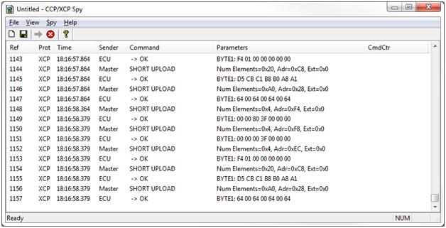
Figure 15. Choose your TestECU protocol type.
For this tutorial, we will use XCP TestECU.vi The simulated ECU device user interface configures the protocol type, CAN Interface, Port, Baudrate, and NI driver (CAN or XNET). For the simulated ECU select:
Protocol: TCP/IP
CAN Interface: CAN1
IP Port: 5555
NI-XNET
Baudrate: 125000
Since the ECU is simulated, you do not need to configure the IP address. The ECU will automatically select the host’s IP address.
Click on the Run Arrow to start to start the XCP ECU Slave simulator.
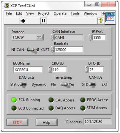
Figure 16. LabVIEW ECU Simulator running.
Notice the ECU Running Boolean indicator is green meaning our Simulated ECU is executing but the ECU is not connected to any master.
Next, add a XCP/CCP Master to your VeriStand System Definition File. In the XCP or CCP Master Settings page, add the existing XCP database example which ships with the ECU Measurement and Calibration Toolkit found in <Installation Drive>\<Users>\<Public>\<Documents>\<National Instruments>\ECU Measurement and Calibration Toolkit\Examples\MS Visual C\XcpECU\XcpECU.a2l
Select the Master Type to be XCP on TCP and the ECU as XCPSlaveSimulator.
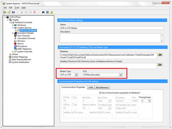
Figure 17. Choose XCP on TCP for Master Type.
Furthermore, in order for the XCP/CCP Master to communicate with the LabVIEW simulated ECU slave, add at least one Characteristic channel to the XCP CCP Master.
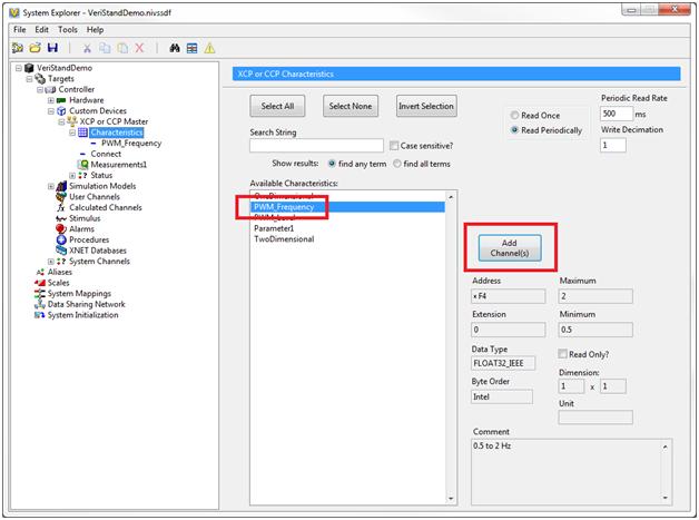
Figure 18. Add Characteristic Channel.
Once you have added all of your Characteristic and Measurements Channels, deploy your System Definition File to your target. Once the System Definition File has deployed successfully, notice the ECU Connected and all other channel access indicators are now green meaning the simulated slave ECU is connected to our XCP or CCP Master.
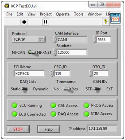
Figure 19. LabVIEW XCP ECU Simulator connected to Master.
Once you have established connection between the simulated ECU and the Master, you can use the setup to learn, test, or debug an ECU Master/Slave network.