Introduction
Modularization and reuse is valuable not only in software design, but also in the creation of circuitry for PCBs. Rather than constantly redesigning a common piece of circuitry, you can save it in a modular and repeatable format known as a Hierarchical Block in Multisim.
Hierarchical Blocks, along with Sub-Circuits, are one of two features offered in Multisim to easily organize and modularize any schematic design. They are similar in that they take sections of a circuit and replace its representation in a design with a block that can be repeated. This block can be treated as a component, and it has input and output pins based upon the net-connections of the original section of circuit it represents. The circuit represented by the block is listed in the design box as a child to the original design project.
Once a Hierarchical Block has been created as a part of your design, you can also repeat its circuit elements in the layout stage. To learn how to repeat the physical layout and traces of these Hierarchical Blocks in Ultiboard, see the related article: Repeating Common Circuits in NI Ultiboard.
Note: There is a subtle difference between Hierarchical Blocks and Sub-circuits: Sub-circuits are saved as a part of the root project and therefore exist only as a part of that root project. A Hierarchical Block, however, is saved as a separate Multisim file and therefore can be considered similar to a component in its ability to be easily re-used and placed in multiple designs.
Creating a Hierarchical Block in Multisim
Hierarchical Blocks can be created in one of three ways:
- Option 1: Define a new circuit where Hierarchical Block Connectors are placed to represent the input and output pins of that circuit.
- Option 2: Use the New Hierarchical Block definition to create a file with the number of input and output pins.
- Option 3: Take a pre-existing circuit and replace part of its circuit representation with a Hierarchical Block.
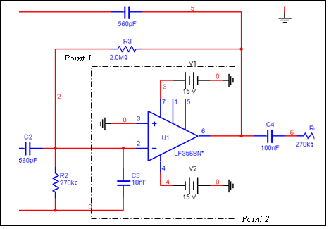
In the following example we will explore Option 3. We will take a section of a shipping example ( SpeechFilter.ms11) circuit and replace it with a hierarchical block named CircuitBlock.
- Open up the example file <installation path>\samples\SpeechFilter.ms11.
- Zoom into the circuit around the Operational Amplifier named U1 (Figure 1).
- Select the components outlined in the dashed black box by left clicking in the work area at Point 1 and drag to Point 2.

Figure 1. Circuitry to be Replaced with Hierarchical Block in Multisim.
- Select Place >> Replace by Hierarchical Block.
- In the Hierarchical Block Properties dialog box enter the name of the new block. It is important to note that this is also the name of the Multisim 11 file that will be created to save the circuit. For this example, name the file CircuitBlock.
- Click the OK button.
Placing the New Block onto the Schematic
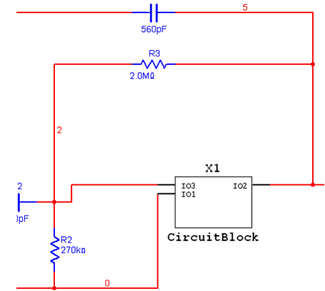
The hierarchical block has now been created. Multisim takes the selected components (Figure 1) and creates a file named CircuitBlock.ms11. In Multisim you will now see the ghosted image of a block attached to the mouse cursor.
Place the block onto the schematic. The output and input pins will automatically connect to the original SpeechFilter circuit (Figure 2).

Figure 2. The new, modularized Speechfilter.ms11 design.
Customizing the Hierarchical Block's Connectors
The block appears similar to a Multisim component with inputs and outputs, a symbol, and a reference description (in this case X1). The pin names can be changed by editing the circuit the block represents. To edit, you can use either of the following methods:
- Method 1: Double-click on the X1 block component. In the Hierarchical Block/Subcircuit dialog box that appears, click on the Edit HB/SC button.
- Method 2: Select the block in the Design Toolbox.
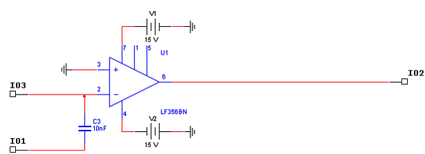
In the Multisim work area, you will now see the circuit you selected in Step 3 (Figure 3).

Figure 3. The Hierarchical Block circuit.
To change the names of the input and output pins;
- Double-click on the I03 Hierarchical Block connector.
- In the Connector dialog box, type IN_1.
- Click the OK button.
You can repeat steps 7-9 for the two remaining Hierarchical Block connectors and re-name them IN_2 and OUT respectively. If you now return to the original SpeechFilter.ms11 design by selecting it in the design toolbox, you will notice the new pin definitions.
The saved Hierarchical Block, CircuitBlock.ms11 is now available to be used many times over in any new circuit. If, for example, you wish to place it into a schematic, you would simply have to select "Place Hierarchical Block From File" in Multisim, and browse to its file name (as it was named in step 5 above). It will be placed as a part of the new design and can be connected to a circuit.