When using a CompactRIO (cRIO) with C Series modules in VeriStand, it may be required to use both Scan Engine and FPGA resources in a project. This is called Hybrid mode and is made possible by using the Scan Engine and EtherCAT Add-on.
This is a tutorial on how to configure both FPGA and Scan resources in NI VeriStand using the EtherCAT Add-on. There are some considerations to keep in mind in order for this set-up to work, addressed in the Additional Information section.
NOTE: For version 2018 and later the Scan Engine and EtherCat Add-on is installed as part of the "custom devices" package included in the larger VeriStand installer as an optional tick box and is installed through NI Package Manager and is officially supported by NI. Prior to version 2018, this add-on was available as a package on Github and not maintained or supported by NI R&D.
In order to use your VeriStand hardware in hybrid mode:
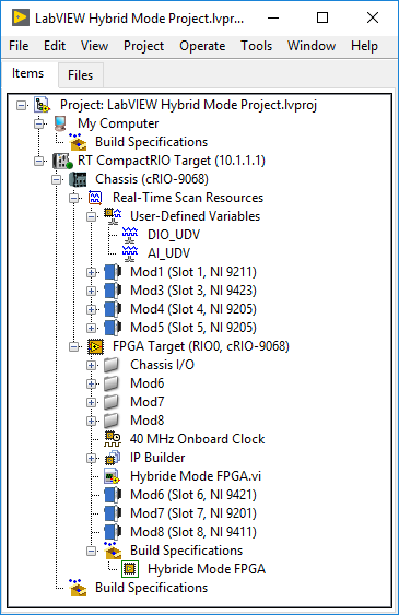
- Create a LabVIEW project for your hybrid mode set up, separating the modules in Real-Time Scan Resources and FPGA Resources.
- Create an FPGA VI and add processing that you need for you FPGA resources.
- Compile the FPGA VI to create a bitfile for this LabVIEW project. This bitfile will have resources for the FPGA-accessed modules as well as set aside resources for the Scan modules.
- Note in the LabVIEW project image below, there are Real-Time Scan Resources in Slots 1, 3, 4, and 5, and there are FPGA resources in Slots 6, 7, and 8. Slot 2 is empty.
- Create a VeriStand project and configure your controller in the system definition (IP address, operating system, etc.).
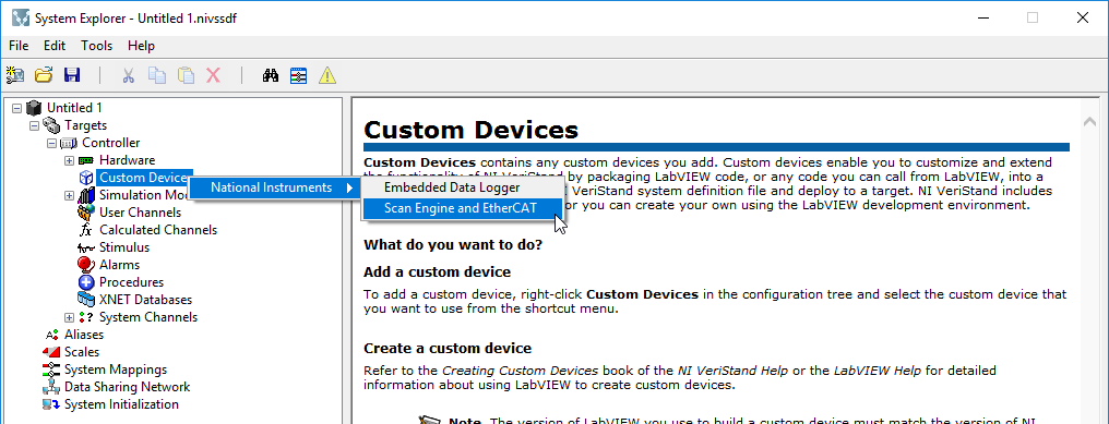
- In the VeriStand System Definition file, right-click on Custom Devices and select National Instruments >> Scan Engine and EtherCAT to add a Scan Engine custom device to your system definition file.
- If you do not see the Scan Engine and EtherCAT option in custom devices, you will need to install the Scan Engine EtherCAT Add-On.
- If you are using VeriStand 2018, you can download the add-on from ni.com downloads via NI Package Manager (NIPM).
- If you are using a prior version of VeriStand, you will need to download the add-on and follow the Installation instruction on the VeriStand Community Page.
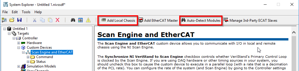
- In the Scan-Engine and EtherCAT configuration window, configure your hardware set-up automatically or manually.
- Using Auto-Detect Modules will detect all local chassis, EtherCAT slaves, masters, and modules connected to your system.
- To manually configure your hardware set-up, select Add Local Chassis.
- If using Add a local chassis, configure your chassis' modules in their associated slots in the windows on the right.
- Note that at this point the slots will either show up as their module name or as "(Empty)".
- Ensure that your modules match the exact configuration as your LabVIEW project and your hardware set up. Otherwise, you will run into communication problems when you add the bitfile to VeriStand.
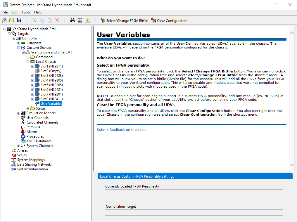
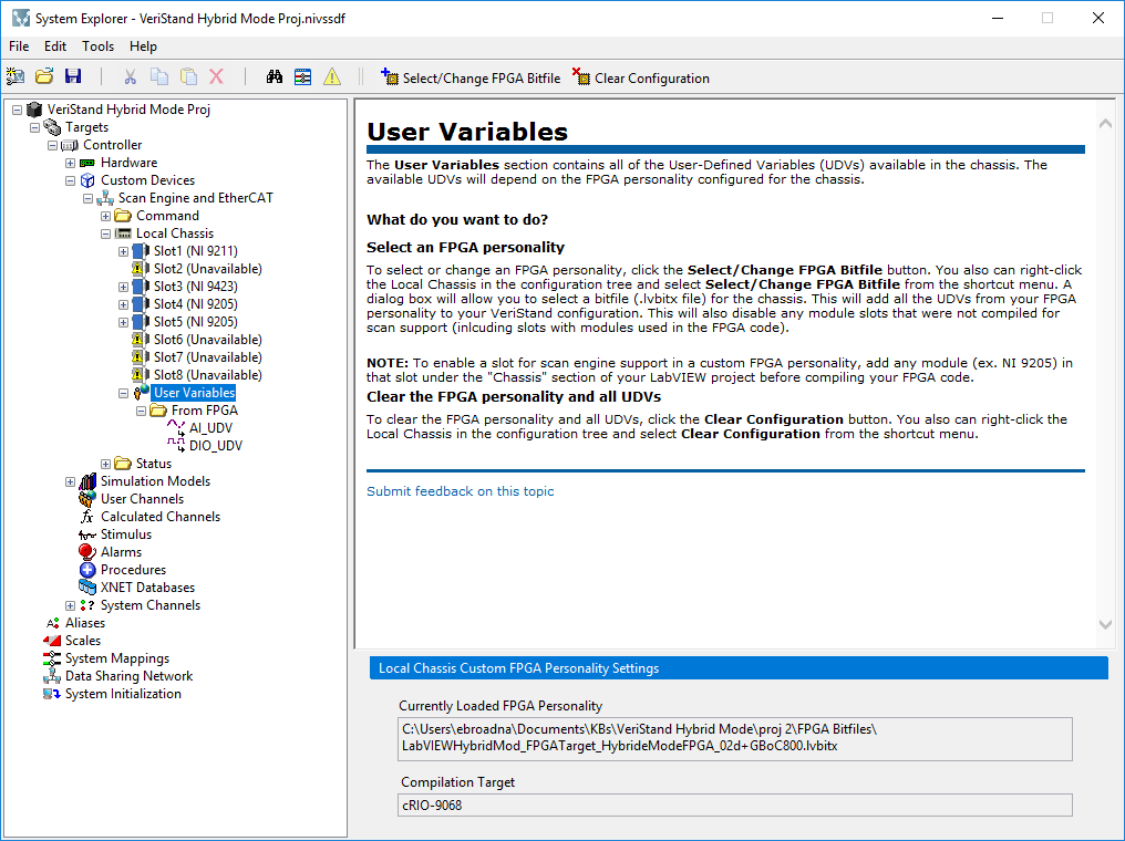
- Select the User-Variables tab in the left panel. In the configuration window on the right, add the bitfile you built in your hybrid LabVIEW project by selecting Select/Change FPGA Bitfile and navigating to the LabVIEW bitfile file path.
- Note that modules change their description in the right panel. Those modules with Scan Resources stay as their Slot number and Module Number. The modules associated with the FPGA now show up as "Unavailable." Note that empty modules show up as "Unavailable" as well.
- Additionally, if your FPGA VI contained User-Defined I/O variables, these variables will show up under User Variables in the right panel.
- If you need up update the bitfile in the VeriStand project, you can change which is loaded in the project by selecting Select/Change FPGA Bitfile.
Your custom device is now set up with Scan resources and FPGA resources, also known as hybrid mode.
Additional Information
You can follow the same method above to create and add a custom FPGA bitfile even if you have no scan resources (i.e. all modules will be accessed by the FPGA).
Considerations:
The FPGA device must have sufficient DMA FIFO channels to support using the device in hybrid mode.
- The number of DMA channels available to the FPGA determines when this configuration is possible.
- Scan Engine mode requires 2 DMA channels, the NI VeriStand FPGA template requires 2 DMA channels, and the XNET modules require 1 DMA channel.
VeriStand can also communicate with the FPGA without using DMA channels, using User Defined Variables (UDVs), or Front Panel Communication. However, do note that due to the limitations of the NI-RIO drivers, the UDVs in an EtherCAT chassis (like an NI 9144 for example) will not be discoverable.
With all of that said, the Scan Engine Custom Device does support having Specialty Digital modules in your cRIO chassis. Specialty Digital modules allow you to define some custom digital behavior (such as counters and pwm outputs) with the scan engine without the need to compile a bitfile. There are some limitations to be aware of though:
- A max of 2 Specialty Digital modules per chassis.
- Speciality Digital is only supported on digital modules with 8 channels or less.
- For PWM outputs, you can only have a fixed frequency for your pulse train. There are 8 selectable frequency options per channel between 1 Hz and 20 kHz, but these values can only be changed at configuration, not run-time. Writing the PWM yourself in FPGA could be more flexible if you need variable frequencies as well as duty cycle.