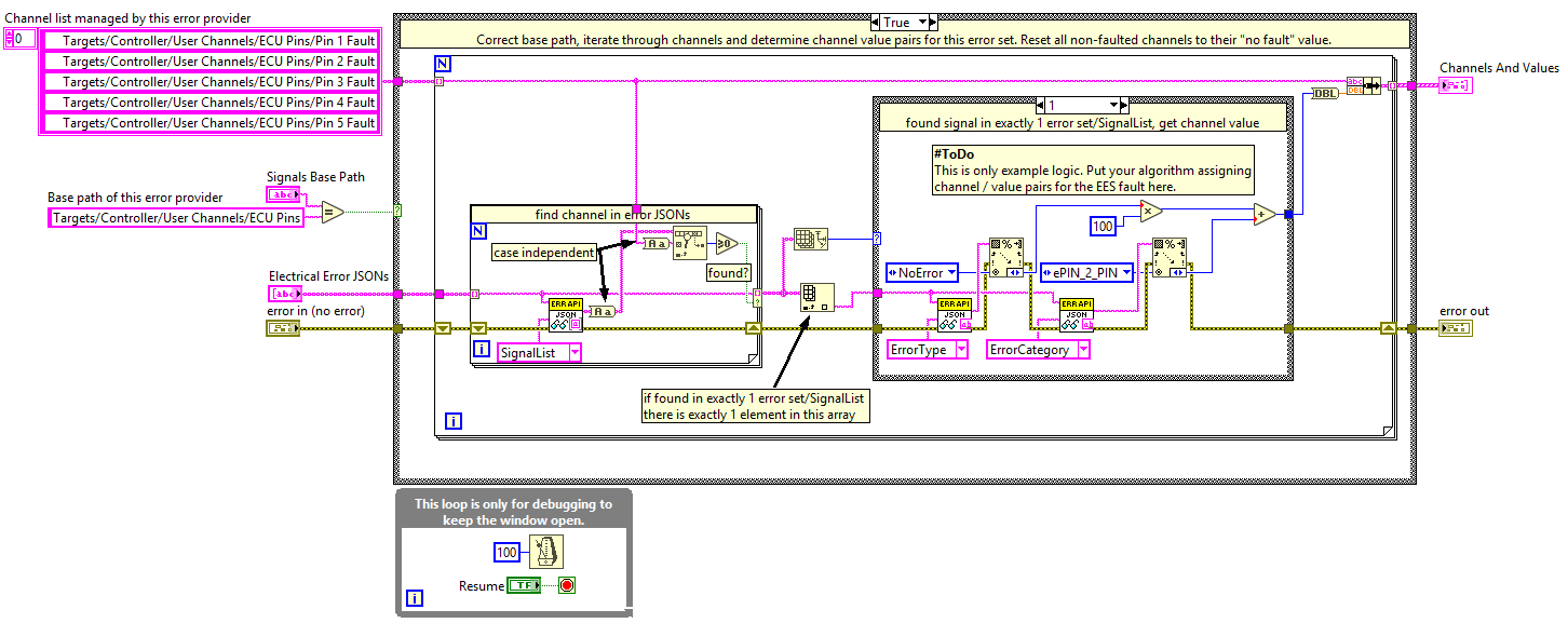
Error Providers are a plugin interface for VeriStand that translates generic faulting sequences (ASAM error configurations) into a sequence of VeriStand channel and value pairs. The key elements of the Error Provider are a translate VI and a XML file. The translate VI implements the logic of how to translate ASAM error sets into VeriStand channel and value pairs. The XML file describes the translate VI to call for the VeriStand system definition tree.
The tutorial contains the following VeriStand specific files (modifications to the original Engine Demo Project are listed).
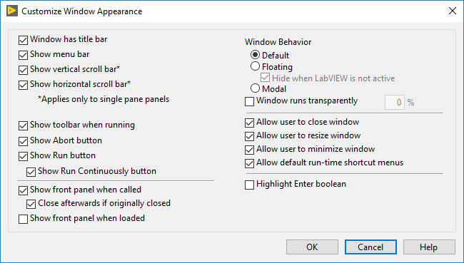
Debugging has been enabled by changing the Window Appearance from “Default” to “Custom” with “Show front panel when called” and “Close afterwards if originally closed” enabled.
 Note:
Note: Starting with ASAM XIL 2.2.0, you must check for the following:
Issue 3812: "Download() and Update() calls shall check that the errors from the error configuration can be applied by the underlying EES system and throw an exception in case an unsupported feature or parametrization is used."
- EES Example VI < LV\Examples\EES example.vi>—An example calling the ASAM XIL EES port using the .NET interface.
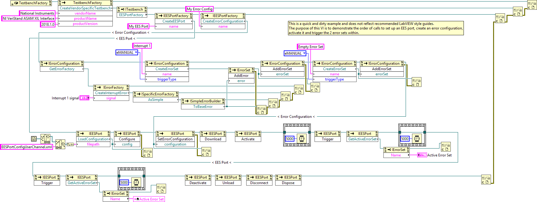
This VI performs the following steps:
- Create an EESPort and ErrorConfiguration.
- Clean up the EESPort.
- Wait 5 seconds, then trigger the second error set. Read the active error set back.
- Wait 5 seconds, then trigger the first error set. Read the active error set back.
- Activate the ErrorConfiguration to call the translate VI logic.
- Download the ErrorConfiguration to the EESPort .
- Note: Complete this step before downloading the ErrorConfiguration.
- Set the newly generated ErrorConfiguration for the EES port.
- Note: This step also launches VeriStand if not already running.
- Load the EESPort Configuration and configure it.
- Create an error set named “Empty Error Set” and add it to the ErrorConfiguration.
- Create an error set named “Interrupt 1,” with a manual trigger containing an interrupt error on “Pin 1 Fault,” and add the error set to ErrorConfiguration.
Steps to Implement or Execute Code
Complete the following steps to use the code in this tutorial.
- Extract the Zip file to a folder. For example, “C:\Users\Public\Documents\National Instruments\EES Tutorial”.
- Edit the “LV\Examples\EESPortConfigUserChannel.xml” file to point to the path of the VeriStand project contained in the extracted folder (“VS\Engine Demo\Engine Demo.nivsproj”).
- Build the error provider from the "LV\Simple User Channel Error Provider\Simple User Channel Error Provider.lvproj"
Note: For VeriStand 2018, a build is already included. - With VeriStand closed, copy the folder “LV\builds\Simple User Channel Error Provider” to “C:\Users\Public\Documents\National Instruments\NI VeriStand 20xx\Error Providers,” where 20xx equals the LabVIEW and VeriStand version used.
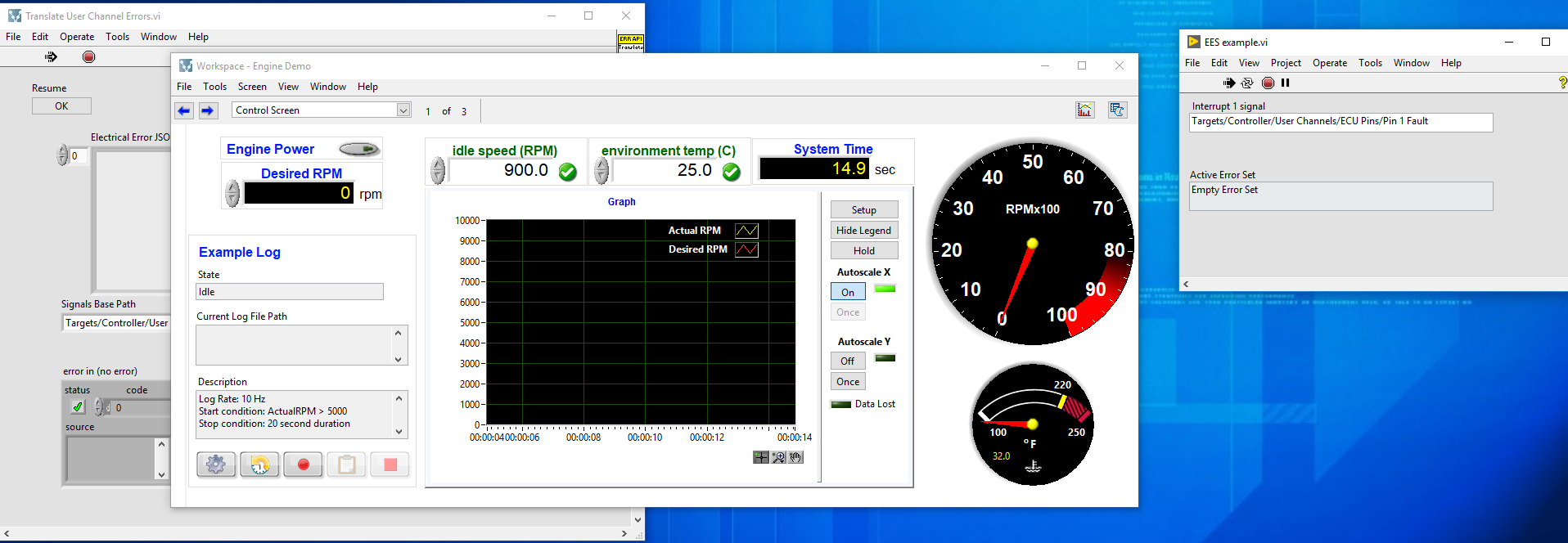
- Run "LV\Examples\EES example.vi".
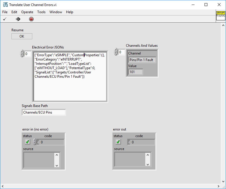
Note: This will also launch VeriStand through the ASAM XIL interface and open the Workspace. - Locate the “Translate User Channel Errors.vi” front panel that pops up in the background (grouped with other VeriStand windows) and click the “Resume – OK” button 8x (4 channel groups times 2 error sets).
Note: This happens because the debugging mode for the error provider is enabled. This is just for demonstration purposes. You can disable debugging mode by removing the debugging while loop from the VI and reverting the window appearance to “default”.
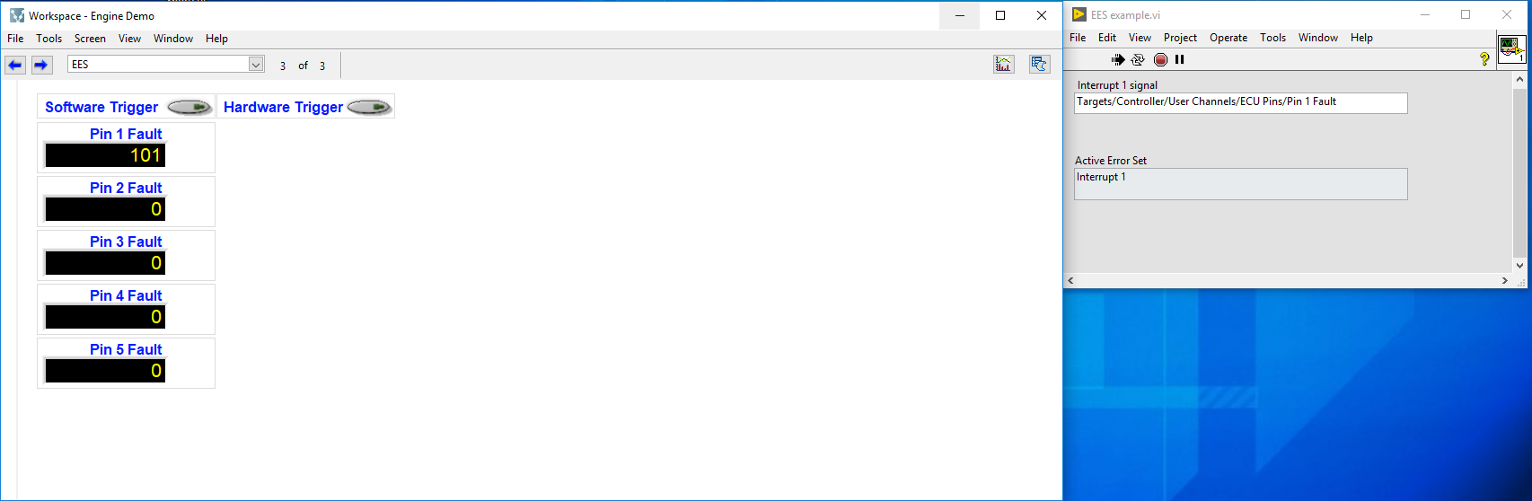
- Observe how the interrupt error for “Pin 1 Fault” is translated.
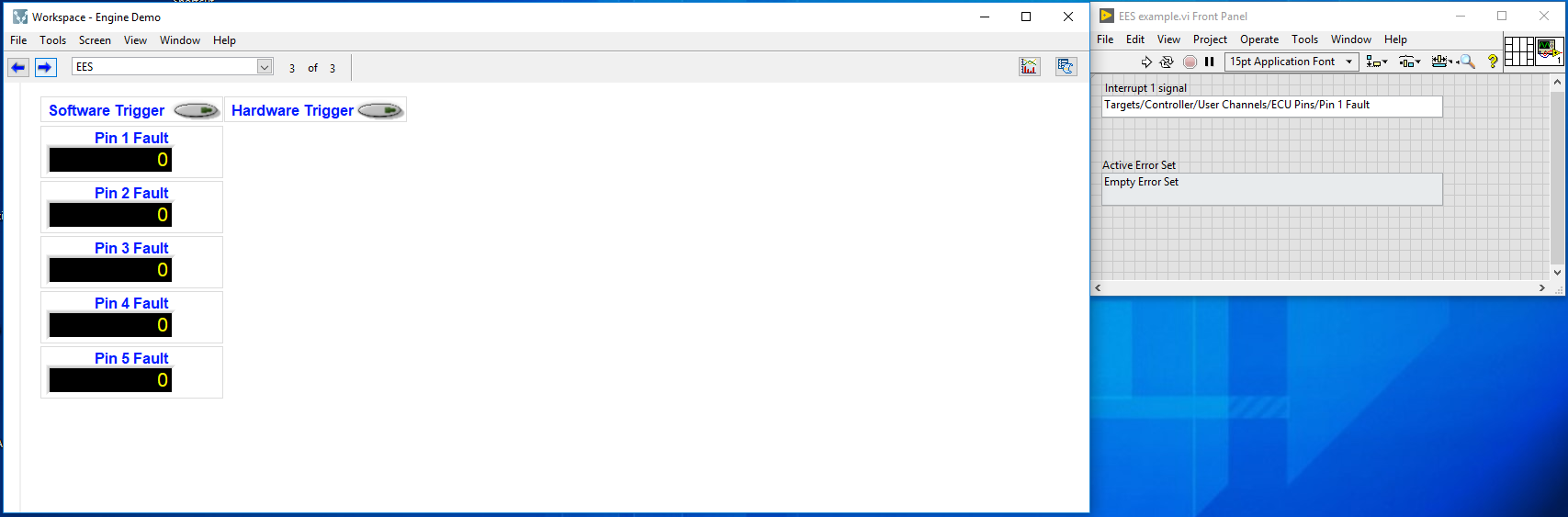
- Switch to the Screen 3 (EES) in the VeriStand Workspace and observe how “Pin 1 Fault” changes from 0 to 101 (the value for interrupt selected in translate VI), and 5 seconds later back to 0 as the second, empty error set is activated.
Additional Information or References
ASAM XIL
ASAM is an automotive development and test systems standardization organization. It is made up of experts, including OEMs, Tier-1s, tool vendors, engineering service providers, and research institutes.
The ASAM XIL API Project’s goals are to:
- Standardize automation interfaces for MIL, SIL, HIL systems.
- Create reusable, test system independent test cases.
- Decouple test automation software from test hardware.
- Enable time synchronization across different subsystems (ports).
The following graphic displays common ports covered by the ASAM XIL API.
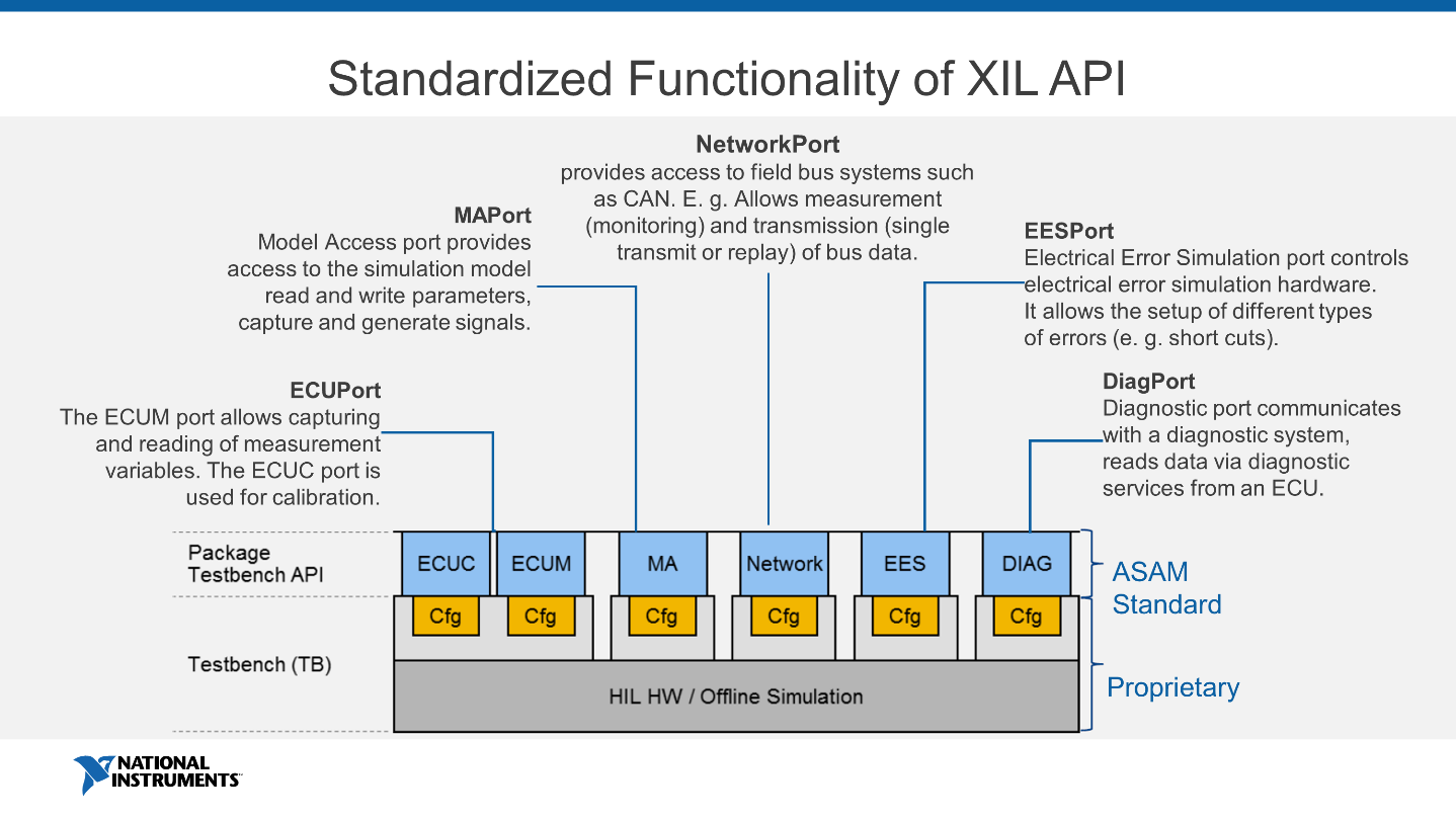
As a first port, the MAport was implemented by most companies supporting XIL. Recently a larger group implemented the Electrical Error Simulation port to provide a standardized access to fault insertion. Frequent cross tests and a unit test suite provided by ASAM ensure seamless interoperability between different tools. ( Link: XIL Cross Test 2017: Freedom to Choose )
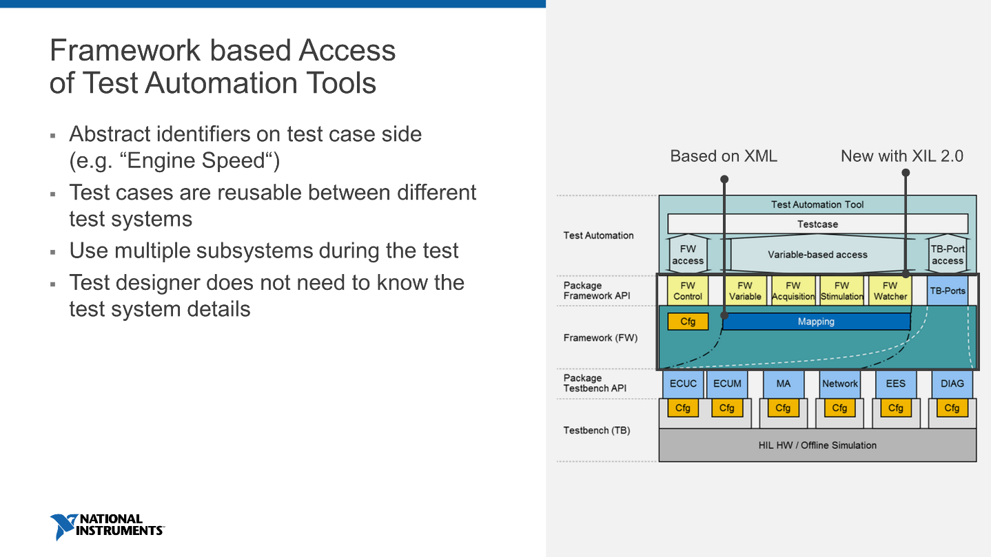
The framework concept introduced in ASAM XIL 2.0 decouples test cases from the underlying test system. All identifiers of a test system, such as the IO channels, diagnostic variables, and fault insertion channels, are abstracted using the framework mapping. With this framework, a test designer does not need to care about where the value comes from. They can design the test case based on the functional requirements and not the specific test system implementation.
The following graphic displays how the framework abstracts the test cases.
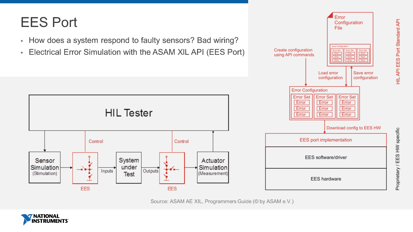
On the left in the graphic, you can see a typical fault insertion setup. It allows to introduce hardware faults like open circuit, short to GND/BATT, resistor faults simulating contact corrosion and others on both input and output pins of the SUT.
ASAM defines an error as a
“…defined disturbance of one or more electrical signals, typically pins of the SUT. E.g. an error may disturb a signal by interrupting the line and replacing it with a resistor. More than one error for different signals may be in effect at the same time, but each signal may only be used once in an error set. All errors that start at the same time are put together in an error set. An EES configuration comprises of a sequence of error sets (see Figure 164).”
The EES Port can be used in two logical modes:
- Static mode, where the error sets defined in the error configuration are triggered in the defined sequence. This mode is to prefer if the timing is most important.
- Dynamic mode, where error sets can be added dynamically to the error configuration while the port is in the states eDOWNLOADED or eACTIVATED. Use this mode if flexibility—i.e. to create variations of test cases during the test execution—is the most important factor.
Note: Dynamic mode was introduced with ASAM XIL 2.0.
Execution of an Error Configuration
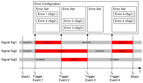
To execute an error configuration, it must be downloaded and started by the test case. When an error configuration is executed, the error sets are executed in the defined sequence (see Figure 165). That means the first error set is activated when the trigger for the first error set becomes true. All other triggers are not considered so far. The errors in the error set stay active as far as the trigger of the next error set becomes true.
The sequence of error sets is defined by the error configuration. It does not depend on the sequence the triggers of the error sets are fired. The triggers only determine when the next error set replaces the currently active error set.
The error configuration must be stopped by the test case using the ASAM XIL API. The last error set remains active if the error configuration is not stopped. To get a defined end of signal disturbance, an empty error set can be used as the last error set in the configuration. Empty error sets can also be used to create error-free phases. Use the figure below as an example for the execution of an error configuration.
If an error is defined in the same way in two consecutive error sets, the error will stay in action. If one error set is replaced by a consecutive error set containing the same error for the same signal, the error will not be restarted or modified.
Triggers in EES
The EES system uses trigger events to switch from one error set to another error set. These triggers are handled by the EES hardware and software. They are not defined by the ASAM XIL API. There are no means to define trigger conditions for EES error sets in the EES port. In an EES error configuration, only the awaited trigger type is defined. The trigger type can be thought of as the trigger input connection of an appropriate hardware. The trigger can also be controlled by the software.
- Manual trigger—The manual trigger is executed by the controlling test script. The EES port offers a method to fire this trigger.
- Hardware trigger—The hardware trigger reacts to an electrical trigger line of the EES hardware. Further details are not defined by the ASAM XIL API. It is expected that the EES hardware will have a hardware trigger input.
- Software trigger—The software trigger reacts to a trigger signal defined in the model or another software part of the XIL system. How the EES system is associated with the software system is not defined by the ASAM XIL API or the EES error configuration.
Electrical Errors
An error is defined by several independent aspects: the error category, the error type, and the option to disturb with or without load.
Error Category
The error category defines how a signal should be disturbed. A signal is interrupted or connected to other signals or a potential (see Figure 166). The way the interruption or short-circuit is provided is not defined by the error category. It is defined by the error type.
The below figure displays how error categories are defined by EES port.
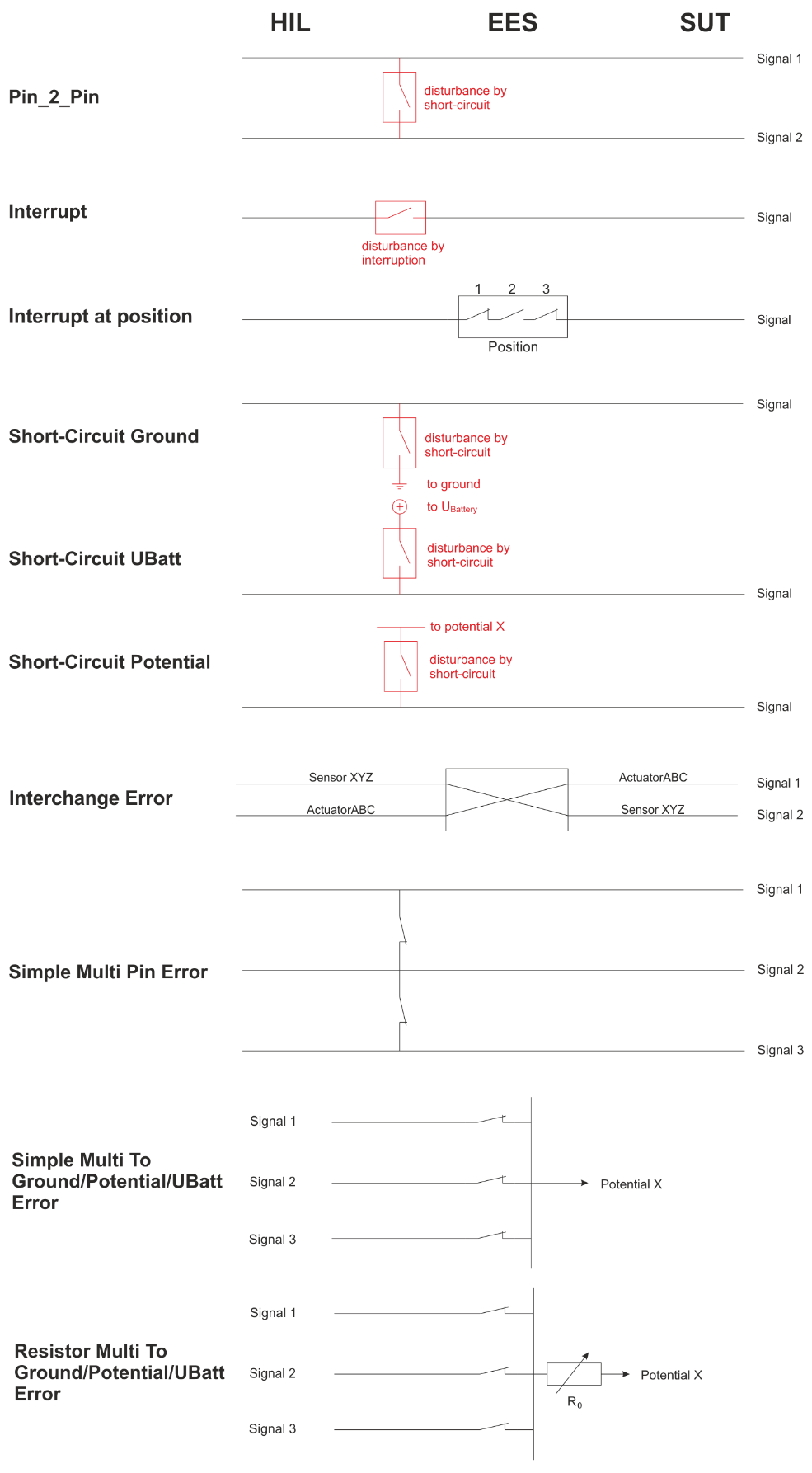
Typically, the error category affects one signal. Only in case of a pin to pin, interchanged, or multi-pin error are two or more signals affected.
The error “short-circuit potential” is the generalized form of a short-circuit error. For this category of errors, the EES hardware must provide additional potentials beside Ubattery and ground. Multiple potentials identified by unique numbers may be supported. Ubattery and ground are covered by separate categories because of their importance.
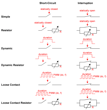
Error Type
The error type defines the disturbance itself. There are several possibilities that differ in the dynamic of the disturbance (static, for a defined duration, controlled by a PWM signal) and the resistance in case of the error (defined resistance or completely open/closed).
The concrete circuit also differs between short-circuit errors and interrupt errors, because in one case the error is caused by closing a connection, in the other by opening the connection. Nevertheless, the idea of an error of the same error type is the same in both cases.
The below figure displays the available error types and the principal circuits used for short-circuits and interrupts.
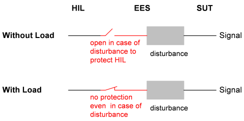
With or without Load
The option “with load” or “without load” is an additional aspect of a signal. This aspect is orthogonal to error category and error type and can be freely chosen for almost every kind of error. Only interruptions do not provide this option because technically it does not make any sense in this case.
Background: If a signal between the XIL and the SUT is disturbed by the EES hardware, not only the SUT has to deal with the disturbance. A short-circuit for example effects the XIL hardware, too. To protect the XIL hardware the EES can open the connection between XIL and EES. Thus, the disturbance has an effect on the SUT but cannot damage the XIL.
The below figure displays the principal circuit of the with/without load protection in the EES hardware.