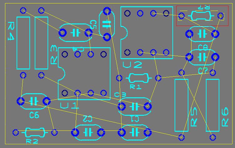
The PCB referred to here was created from the example schematic available in the samples directory found in your base Multisim installation path. (<installation path>\Samples\SpeechFilter.ms10).
Assume that you have decided to remove R7 from the layout. You will first delete the footprint in the sample layout and then annotate the corresponding Multisim schematic to reflect change.

Figure 1: Sample Ultiboard Layout
Delete R7 from the PCB Layout.
- From Ultiboard select resistor R7 which is highlighted in red in Figure 1.
- Delete the resistor R7 by pressing the Delete button on the keyboard.
- Save the changes made by Selecting File > Save. (In this example the file is saved to <install path>\Sample\SpeechFilter.EWPrj).
- When changes are made to a layout design, these changes are saved to a .log file in the same file path as the Ultiboard (.ewPRJ) file. Multisim will compare this log file with the current schematic's netlist to find any changes that were made.
To back annotate this change:
- In Multisim open the original schematic file used to create the PCB layout that you just modified.
- Select Transfer >> Backannotate from Ultiboard.
- Browse to the path where the layout file is saved and select the Ultiboard log file (.log) named Speechfiler.log.
- Click the Open button
- Multisim will display a list of changes to be annotated from Ultiboard.
- In this case resistor R7 is being deleted. Click OK.
Resistor R7 has been deleted from the schematic.