Simulation With Real-World Signals
In this example, a heartbeat signal is acquired using VirtualBench and is imported into a simulated circuit of a signal conditioning amplifier to be evaluated using Multisim. This section goes over the process of exporting measurements from VirtualBench and importing them into Multisim:
- Using VirtualBench, acquire a signal. As can be seen in Figure 1 below, this example is acquiring a heartbeat signal from an ECG sensor device.
-
In the Mixed-Signal Oscilloscope settings menu, select Acquisition » Sample as seen in Figure 1. Multisim requires that waveforms use this mode.
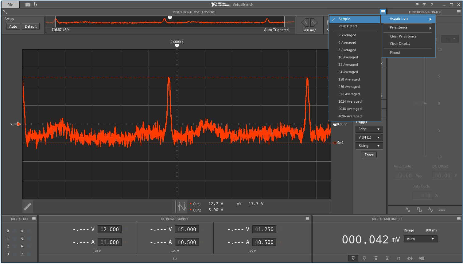
Figure 1. Change Acquisition Mode to “Sample” Before Exporting Measurements from VirtualBench
- In the VirtualBench application, go to File » Export Data… or simply press Ctrl-X to save the raw measurement data to a .csv file to a specific directory on your computer.
- To load your waveform in Multisim, you need to download the attached library called VB_Multisim_Library.llb . The library allows you to import VirtualBench measurements into Multisim. This library needs to be installed to \National Instruments\Circuit Design Suite\LVInstruments to function properly.
- Multisim is the only circuit simulation tool that offers the capability of creating custom sources, simulation analyses, and instruments. With this custom library created in LabVIEW, VirtualBench measurements can be seamlessly integrated in a design simulation of a signal conditioning amplifier.
-
Open Multisim; the LabVIEW Instruments menu and toolbar are displayed at the top of the window as seen in Figure 2. If Multisim was already started before you completed step 5, then you need to restart Multisim.
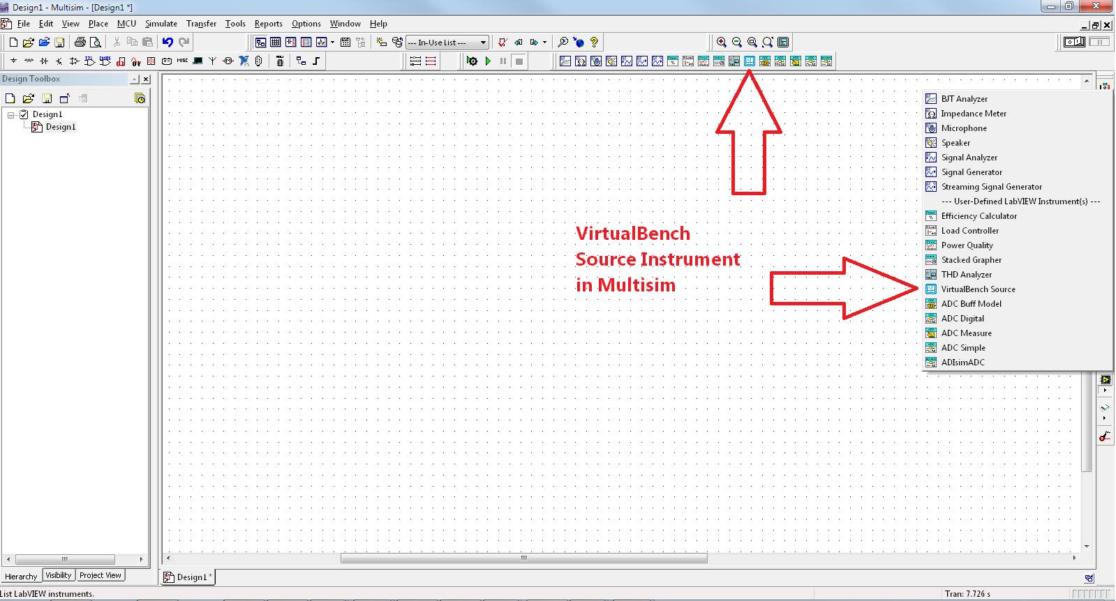
Figure 2. Location Where the VirtualBench Instrument is Loaded in Multisim
-
Drag and drop the VirtualBench device into your design to use the device as a signal source. See Figure 3.
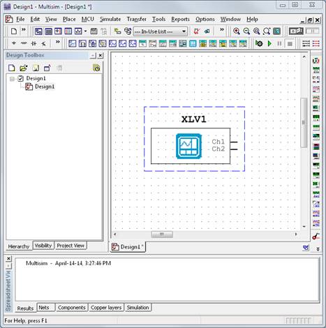
Figure 3. VirtualBench Device on a Multisim Schematic
-
Double-click on the device. In the File Name field, navigate to the exported .csv measurement file saved in step 4. Click OK. It will now load the signal and provide a preview. You also have the option to repeat the data to run simulation times longer than the acquired stream.
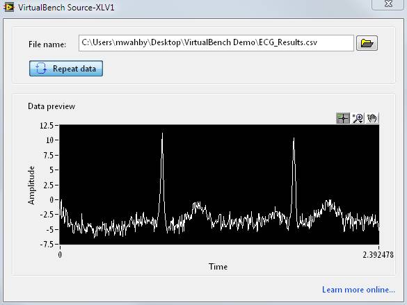
Figure 4. Exported ECG Signal from VirtualBench Loaded in Multism
-
Now the signal is ready to be used inside Multisim for further design optimization. In this example, we are using the attached schematic. Connect the device on the schematic to the active filter circuit as shown in Figure 5.
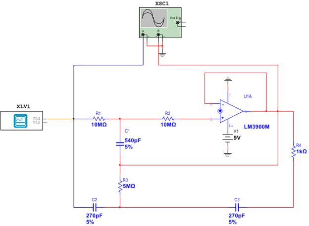
Figure 5. Multisim Circuit With a VirtualBench Source
- Click the PLAY button to run an interactive simulation in Multisim and to use this data in simulation. Instead of simulating your circuitry with ideal signals, you are now performing a simulation with real-world signals that include impairments from the environment. This helps you accurately validate the overall circuit performance under real-world conditions and increases your confidence in your design before fabricating it.
The output of the simulation is shown on the oscilloscope instruments connected to the circuit as shown in Figure 6.
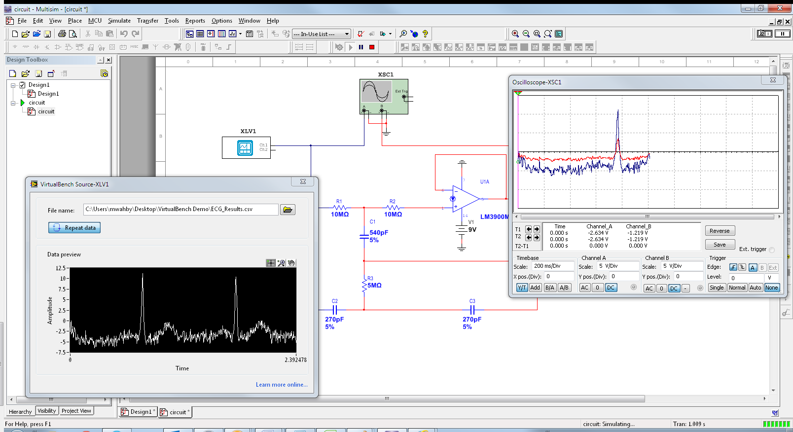
Figure 6. Interactive Circuit Simulation With Real-World Signals.