NI Multisim to Mentor Graphics PADS Layout Netlist Export
The export ability from NI Multisim 10.0 to Mentor Graphics PADS is a product of the strengthened design community that the NI Electronics Workbench Group has cultivated to provide a platform open to working with partners in the EDA industry.
The following article discusses how to set up, transfer, and design with NI Multisim and Mentor Graphics PADS ® Layout (2005).
The process of transfer to Mentor Graphics PADS consists of two initial configuration steps that must be completed once, and a third export step that can be applied to any design:
Step 1: Initial Setup of Mentor Graphics PADS Layout
To ensure the NI Multisim schematic transfers a complete design to PADS, the PADS layout tool must be setup to properly accept the Multisim netlist. This is done by importing a group of Multisim-defined footprints into the PADS footprint library. This setup step ensures that the Multisim netlist definitions have an appropriate footprint to map to in PADS, maintaining the integrity of the netlist throughout the transfer process.
To transfer the Multisim footprints into PADS:
- Open the PADS Layout tool.
- Select File >> Library to display the Library Manager.
- Click on the Create New Lib... button and name the library (e.g. NI Multisim Library).
- Under the Library drop-down list make sure the newly created library is selected.
- Click on the Decals button and click the Import button.
- Browse to C:\Program Files\National Instruments\Circuit Design Suite 10.0\PADS\ and select the Generic.d file
- Click the OK button
- Click on the Parts button
- Click on the Import button.
- Browse to C:\Program Files\National Instruments\Circuit Design Suite 10.0\PADS\ and select the Generic.p file
- Click OK.
Mentor Graphics PADS Layout is now ready to import an NI Multisim schematic.
Step 2: NI Multisim Database Mapping
All schematic symbols in the NI Multisim database map to a real PADS footprint or a generic PADS footprint.
The generic footprint is an artificial footprint that PADS can identify and serves to preserve a netlist connection during the transfer process. Without the generic footprint, PADS could possibly encounter the name of a footprint in the Multisim netlist that it cannot identify and therefore would automatically delete it from the design.
Generic footprints are defined in Multisim and are imported into PADS via the steps outlined in the Initial Setup of PADS Layout section of this article.
To understand how Multisim maps its database components to real and generic PADS footprints, view the Select a Footprint dialog box (Figure 1). Notice that for the IPC-2221A/2222 component (figure 1, red box), the PADS Footprint column contains the name of a real footprint, the DIP14. Conversely, the IPC-SMT-783 component (figure 1, blue box) is mapped to a generic PADS Footprint (GENERIC2) which has two pins but is not necessarily a commercial footprint.
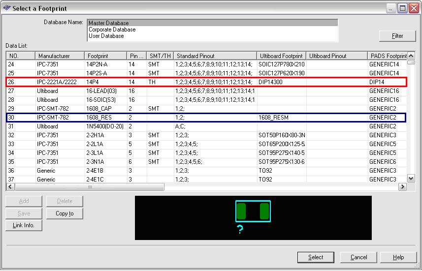
Figure 1: Select a Footprint
Re-mapping
Components that are mapped to a generic PADS Footprint can be easily changed, so that they are remapped to the name of a commercial PADS footprint.
To re-map a Multisim component to a real PADS footprint;
- Open up the spreadsheet view in the Multisim environment by going to View >> Spreadsheet View
- Select the Components tab
- For the required component, double-click in the Footprint column
- In the Edit Footprint dialog box click on the Select From Database button
In the Select a Footprint dialog box notice that the default footprint associated with the component is in the Master Database, which is a read-only database. To re-map to a real PADS Footprint the footprint must first be saved to the user database so that an edit can be made to this database entry. Once in the user database, information such as the PADS mapping can be easily changed.
- Select the appropriate footprint in the dialog box (for example, IPC-SMT-782, as shown in figure 1)
- Click on the Copy To button
- In the Set Parameters dialog box set the Database Name to User Database (figure 2)
- As you return to the Select a Footprint dialog box, set the Database Name field to User Database.
- Select the name of the footprint, and left-click once in the PADS column
- Type the name of the real PADS footprint in the column (this name will exactly match the name of a footprint available in the PADS database).
- Click on the Select button.
- Click on the OK button.
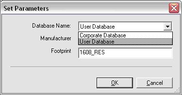
Figure 2: Set Parameters
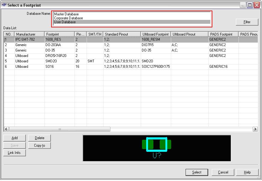
Figure 3: Re-map Footprint
The User Database now contains the name of the re-mapped footprint (for example IPC-SMT-782).
The above re-mapping process can be repeated for the various footprints used in the design process, thereby populating the User Database with the names of the real PADS footprints that are to be used in the design process.
Step 3: How to Transfer to Mentor Graphics PADS Layout
To transfer a NI Multisim schematic to the Mentor Graphics PADS layout tool;
- Complete a schematic in NI Multisim
- Select Transfer >> Export to PCB Layout (Figure 4)
- Save as type PADS Layout 2005(*asc)
- Name the layout file
- Click on the Save button.
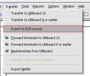
Figure 4: Transfer Menu
When in PADS Layout
After exporting to PADS Layout, some components may have still been exported with a generic footprint (if not changed with the process outlined in the NI Multisim Database Mapping section) rather than the specific industry standard package for that component.
To choose the appropriate footprint in PADS, select the generic footprint, and replace with the specific package.
Limitations
NI Multisim is only able to transfer a completed schematic netlist to the Mentor Graphics PADS Layout tool. Additional integration, such as back annotation, forward annotation and cross-probing to manage a project throughout various design iterations are unavailable at this time.