IEC 61131-3 Programming Standard
The IEC 61131-3 is an international standard for Programmable Logic Controllers (PLCs). The standard defines basic software architectures and programming languages of the control program within PLCs. The standard defines two graphical and two textual programming languages:
- Ladder Diagram (LD)
- Function Block Diagram (FBD)
- Structured Text (ST)
- Instructions List (IL)
- Sequential Function Chart (SFC)
IEC 61131-3 is vendor independent and very well established in Europe, but gaining popularity in North America and Asia as the programming standard for industrial and process control. The use of standard programming languages has a positive impact on the software life-cycle that includes requirements analysis, design, construction, validation, installation, operation, and maintenance. The integration of IEC 61131-3 programming languages with customizable and flexible NI hardware allows the incorporation of specialized I/O such as motion or machine vision capabilities while preserving previous investments through reuse of existing code. This integration is facilitated by using the CODESYS IDE for the development and deployment of IEC 61131-3 languages to NI Linux Real-Time devices such as CompactRIO and Single-Board RIO.
CODESYS IDE
CODESYS is a highly adopted development environment for programming controlling applications using the IEC 61131-3 standard. CODESYS supports all 5 programming languages part of the standard as well as included compilers to transform the application code into machine code which is then downloaded into the controller. This platform-independent development environment is compatible with the PLCs and automation components of over 250 companies including National Instruments.
For embedded developers creating smart machines or industrial equipment, CODESYS provides a common system that uses common software. This allows the integration of NI embedded devices in charge of specialized tasks with existing controllers or automation components. The common development environment let’s system designers work with any of these components and facilitates code reuse and debugging tasks.
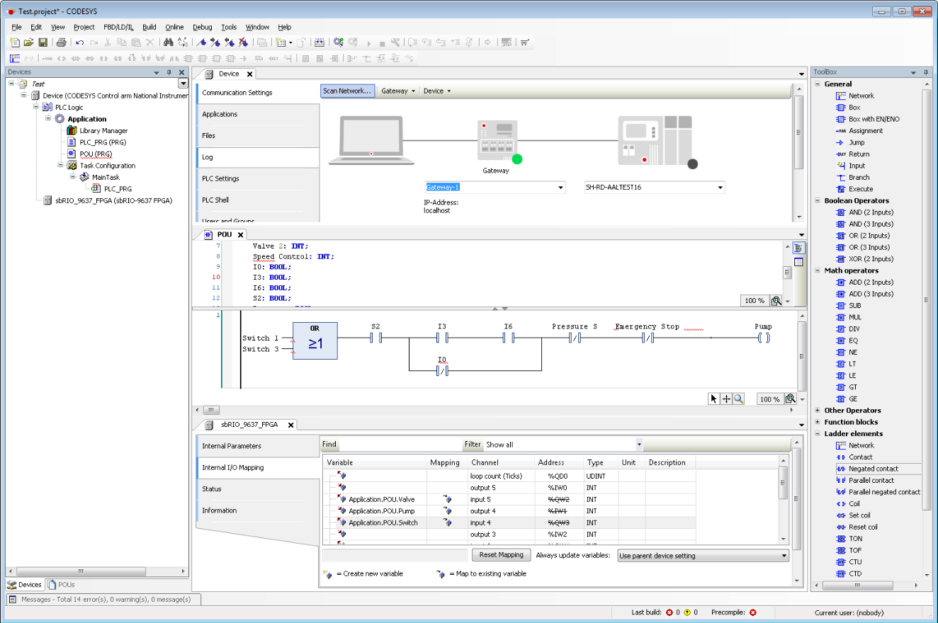
Figure 1: The CODESYS IDE provides a common system and software for a variety of industrial automation devices
CODESYS is used in a variety of automation applications from traditional process automation to factory, mobile and energy automation. To learn more about CODESYS please visit the link below.
>>Learn more about the CODESYS IDE
LabVIEW FPGA IEC 61131-3 Interface Utility
The LabVIEW FPGA IEC 61131-3 Interface Utility allows industrial automation code defined by the IEC 61131-3 standard to interface with the FPGA fabric on NI Linux Real-Time devices through the 3S CODESYS IDE. This utility allows you to access the I/O from a compiled LabVIEW FPGA bitfile through several industry-standard languages such as Ladder Logic, Structured Text, and Function Block Diagram. Additionally, you can deploy and compile IEC 61131-3 code and FPGA bitfiles directly through the CODESYS IDE.
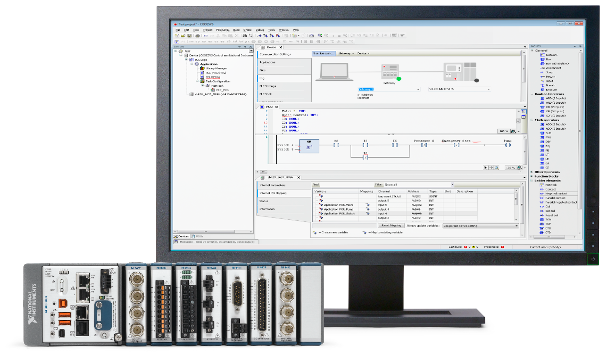
Figure 2: The LabVIEW FPGA IEC 61131-3 Interface Utility allows IEC 61131-3 code to interface with FPGAs on NI embedded devices
The following diagram demonstrates the flow of data between software and hardware components for deploying a CODESYS application to an NI Linux Real-Time target.
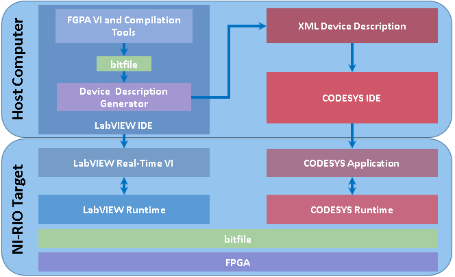
Figure 3: Data flow for the LabVIEW FPGA IEC 61131-3 Interface Utility
The following list describes the components in the diagram:
Host Computer—The computer that runs necessary software components.
LabVIEW IDE—The IDE you use to develop and manage VIs.
FPGA VI and Compilation Tools—The FPGA VI is the VI that defines the I/O of the NI Linux Real-Time target. The LabVIEW compilation tools translate the FPGA VI into binary data that you can download and run on the NI Linux Real-Time target.
bitfile—A compiled version of the FPGA VI.
Device Description Generator— Tools that generate a custom device description for the CODESYS IDE to access the I/O of the NI Linux Real-Time target.
XML Device Description—An XML file that contains information about the controls and indicators in the FGPA VI.
CODESYS IDE—The IDE you use to build and deploy CODESYS applications.
NI Linux Real-Time Target—NI Linux Real-Time hardware that runs the code you create with LabVIEW and CODESYS.
LabVIEW Real-Time VI—The VI that runs on the NI Linux Real-Time target and communicates programmatically with the FPGA VI.
LabVIEW Runtime—The LabVIEW Run-Time Engine that includes the libraries and other files necessary to run basic application types built in LabVIEW.
CODESYS Application—The executable control program you deploy to the NI Linux Real-Time target using CODESYS.
CODESYS Runtime—The CODESYS runtime system that offers functions for the NI Linux Real-Time target to communicate with the CODESYS programming system.
bitfile—A compiled version of the FPGA VI that you download to the NI Linux Real-Time target.
FPGA—Reprogrammable chips.
The rest of this document goes through the basic steps of creating a deploying an application with the LabVIEW FPGA IEC 61131-3 Interface Utility.
Creating and Compiling a LabVIEW FPGA Application
The first step to interface with the FPGA on NI Linux Real-Time devices is to create an FPGA application. This can be done using LabVIEW and the LabVIEW FPGA Module. To learn more about creating LabVIEW FPGA applications please visit the link below.
>>Creating LabVIEW FPGA Applications.
Once the application is complete it must be compiled to get the Bitfile required to import the FPGA configuration into the CODESYS IDE. To learn more about LabVIEW FPGA compilation options please read the resource below.
>>LabVIEW FPGA Compilation Options.
Once the Bitfile is created it can be transferred to the CODESYS IDE.
Using the XML Device Description
Use the XML Device Description tool included with the LabVIEW FPGA IEC 61131-3 Interface Utility to generate and XML file suitable for CODESYS to interpret the FPGA application as a new device.
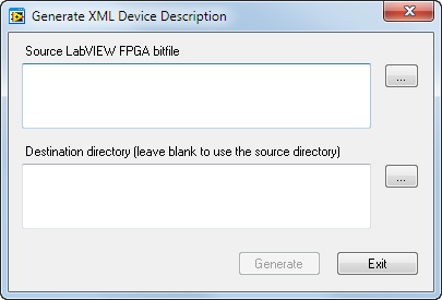
Figure 4: Generate XML Device Description
1. In LabVIEW, select Tools»IEC 61131-1 Interface Utility»Generate XML Device Description to launch the Generate XML Device Description dialog box.
2. In Source LabVIEW FPGA bitfile, specify the path to your FPGA bitfile. You can also use the LabVIEW FPGA IEC 61131-3 Interface sample project to generate an FPGA bitfile. Access this sample project by selecting File»Create Project in LabVIEW and selecting LabVIEW FPGA IEC 61131-3 Interface in the IEC 61131-3 Interface category. Refer to the sample project documentation in the Project Documentation folder of the project for more information about this sample project.
3. In Destination directory, specify a directory to save the XML device description file. Click Generate.
4. Click Exit to close the Generate XML Device Description dialog box.
LabVIEW FPGA Data Types Supported by CODESYS
If an FPGA bitfile contains data with types not supported by CODESYS, the LabVIEW FPGA IEC 61131-3 Interface Utility omits the data when you generate an XML device description from the bitfile. CODESYS supports the following LabVIEW FPGA data types:
-Signed integer
-Unsigned integer
-Single-precision, floating-point number
-Enum
-Ring
-Boolean
-1D Array of the above-listed data types
-Host to Target and Target to Host DMA FIFOs with the following data types:
-Signed integer
-Unsigned integer
-Single-precision, floating-point number
-Fixed-point number
-Boolean
Building and Deploying an Application in the CODESYS IDE
After installing and configuring the software and hardware, you build a CODESYS application and deploy it to the NI Linux Real-Time target. After deploying, you can use the IEC 61131-3 programming languages to program the NI Linux Real-Time target.
Note Before proceeding, complete sections 4 and 5 of this document using the LabVIEW FPGA IEC 61131-3 Interface sample project described in step 2 of section 5. The following steps utilize the attached CODESYS example project and assumes that the FPGA VI included in the sample project was not modified from its original state.
- Download and extract the attached zip file, which contains an example CODESYS project.
- Open the Chassis Temperature Reading CODESYS project from the CODESYS folder.
If the project opens with missing library errors and the two devices display as unknown devices, you likely installed the CODESYS IDE after installing the LabVIEW FPGA IEC 61131-3 Interface Utility. To resolve this issue, select Tools»Device Repository. Click Install to launch the Install Device Description window. Install the NI PLC device description files at C:\Users\Public\Documents\National Instruments\LabVIEW 2017 FPGA IEC 61131-3 Interface Utility\Examples. - Select Tools»Device Repository to launch the Device Repository dialog box.
- Click Install to launch the Install Device Description window.
- Choose the XML device description file you generated. Click Open.
- Make sure that the device description appears under the Miscellaneous category in the Device Repository dialog box. Click Close.
- In the Devices view, double-click Device (National Instruments-ARM-Linux) or Device (National Instruments-x86-Linux) depending on the target type that you are using.
- On the Communications Settings page, click Scan Network to launch the Select Device window. Select the NI Linux Real-Time target and click OK. To discover the target, the target must be on the same subnet as the host PC and the Recommended Software Set included with the deployment license must be installed on the target.
- On the Files page, browse to and select the FPGA bitfile in the Host view. Click the right arrow button to copy the bitfile to the NI Linux Real-Time target.
- Right-click on Device (National Instruments-ARM-Linux) or Device (National Instruments-x86-Linux) and select Add Device.
- Under the Miscellaneous category in the Device Repository dialog box, select the device description that you added previously. Click Add Device and Close.
- Double-click the device description you added in the Devices view. On the Internal I/O Mapping page, map the USER FPGA LED channel to the Application.PLC_PRG.userLED variable and the Chassis Temperature channel to the Application.PLC_PRG.raw_chassisTemp variable. If you click in the blank variable cell, you can type in the variable name, or navigate to it using the … button.
- Under the Device and PLC Logic items, right-click on Application and select Login. If asked to download the application, select Yes.
- Double click PLC_PRG under the MainTask Task Configuration.
- Click the Start arrow.
- The chassis temperature should update as expected and the user LED should respond based on the temperature’s relationship to the specified threshold. Read the PLC_PRG comments for more details.
- Double-click the threshold value and enter a value greater than the chassis temperature. Click OK and press <F7> to change value of the User LED.
Deploying to an NI Linux Real-Time Target
When deploying your application, this is done the same way as with any other device in CODESYS. The IEC 61131-3 along with the FPGA bitfile will be automatically deployed to the right locations in the NI Linux Real-Time target.
Note Deployment requires a IEC 61131-3 Deployment License for NI Linux Real-Time .