Prerequisites
Before starting this tutorial, NI recommends reviewing the information in MATLAB, Simulink, and LabVIEW FPGA: Importing HDL Coder into LabVIEW FPGA Designs.
Note: This tutorial assumes familiarity with MATLAB and focuses on the workflow within LabVIEW. For more information and examples of MATLAB, refer to the official documentation and the MathWorks website.
Install the following software with the specified version. Other versions may also work but the UI might be different.
- MATLAB® R2019a
- Fixed-Point Designer™
- MATLAB Coder™
- HDL Coder™
- Signal Processing Toolbox™ recommended
- DSP System Toolbox™ recommended
- HDL Verifier™ recommended
Modifying a MATLAB Function and Testbench
- Create a new folder for storing the MATLAB files and exports.
- Launch MATLAB.
- In MATLAB, browse to the folder created in step 1 using the Browse for Folder button.
- In the Command Window, run the following commands to copy the tutorial designs to the current directory:
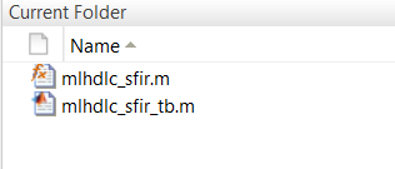
copyfile(fullfile(fullfile(matlabroot,'toolbox','hdlcoder',... 'hdlcoderdemos','matlabhdlcoderdemos'),'mlhdlc_sfir.m'),pwd);copyfile(fullfile(fullfile(matlabroot,'toolbox','hdlcoder',... 'hdlcoderdemos','matlabhdlcoderdemos'),'mlhdlc_sfir_tb.m'),pwd);After doing so, the two files should appear in the current folder:
- Modify the FIR filter to add the Valid In and Valid Out interface signals which will be used to interface with the LabVIEW FPGA VI. Open mlhdlc_sfir.m in the Editor.
- Add a valid_in input and valid_out and x_valid_out outputs to the function definition. These signals will be used to represent the status of the inputs and outputs of the function in the LabVIEW FPGA design.

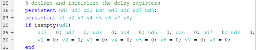
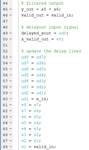
- Next, add persistent variables to store the new signals between function calls and translate the valid_in to the two valid_out signals.
a. The valid_out signal should update at the same point that y_out becomes a valid value. Since the function and test bench assume that y_out is valid after any call of the function, no persistent variable is needed.
b. The x_valid_out signal should receive the same amount of delay as the delayed_xout variable. To accomplish this, add another chain of delay registers:
- Add logic for each new variable. For the valid_out and valid_signal variables, this is as simple as treating the valid_signal variable as a temporary variable between the valid_in and valid_out parameters. For the x_valid_out variable, the structure should mimic the existing delay lines for the delayed_xout variable.

 Note:
Note: This method of handling the valid signals assumes that once valid data is given to the filter, every subsequent cycle valid input is available until the filtering is complete. If cycles of invalid data will occur between cycles of valid data, NI recommends using handshaking such as AXI in the top-level interface.
- Save the changes to mlhdlc_sfir.m.
- Now that the function has been modified, the corresponding test bench should be updated as well. Open mlhdlc_sfir_tb.m in the Editor.
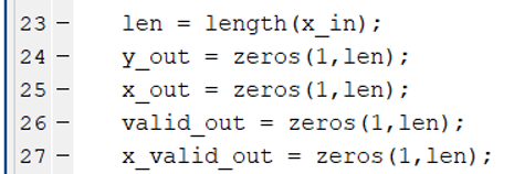
- In the test bench, add declarations for new output variables to contain the Valid Out signals.
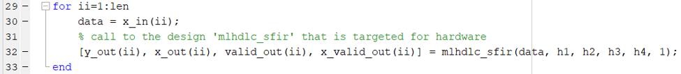
- Update the test bench call to the function being tested to include the new inputs and outputs. Note that valid_in is given a constant value of 1.
- Save mlhdlc_sfir_tb.m.
- To verify that the function stills runs as intended, run the test bench from the Command Window and confirm that the output matches the image below.

Generating VHDL Code with HDL Coder
With the modified function and test bench, you can now create the HDL Coder export, which involves creating an HDL Coder project, determining a fixed-point representation for the function, then configuring the HDL generation parameters.
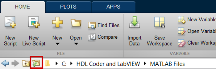
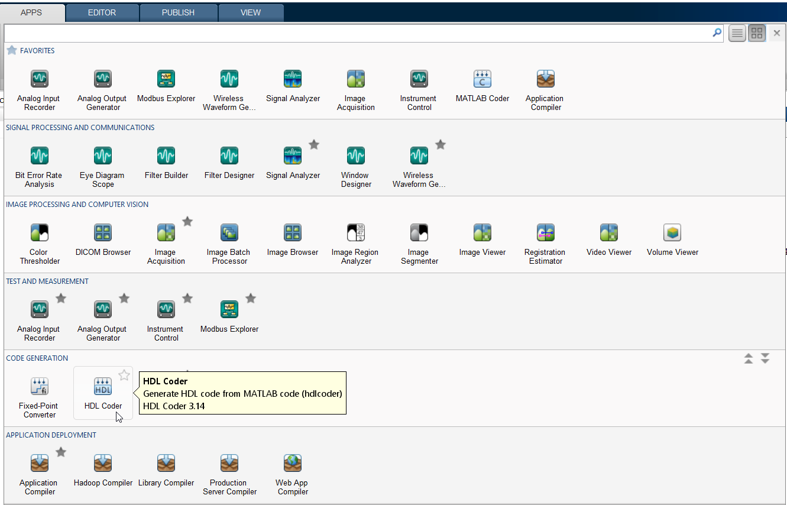
- In MATLAB, create a new HDL Coder project by selecting HDL Coder from the Apps menu.
- Provide a name for the project and confirm that it is saved in the same location as the function and test bench
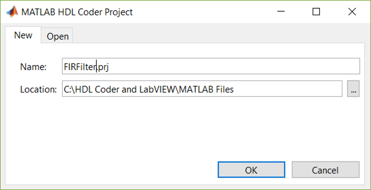
- Click OK. An HDL Code Generation view opens with the project active.
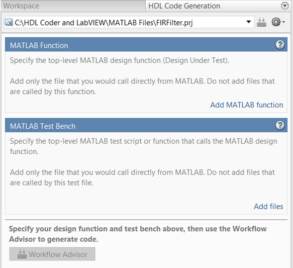
- Click the Add MATLAB function option and select the function to be exported. Click Open.
- Click the Add files option under the MATLAB Test Bench section and select the test bench. Click Open.
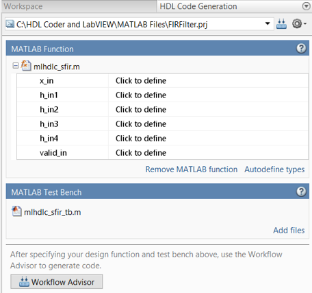
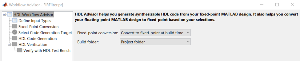
- Click the Workflow Advisor button to launch the Workflow Advisor window for HDL Coder.
- In the HDL Workflow Advisor category, confirm that the Fixed-point conversion option is set to Convert to fixed-point at build time.
- Switch to the Define Input Types category, then click Run to define the input types automatically based on the test bench. A checkmark appears next to the category in the tree view when the input types are defined.

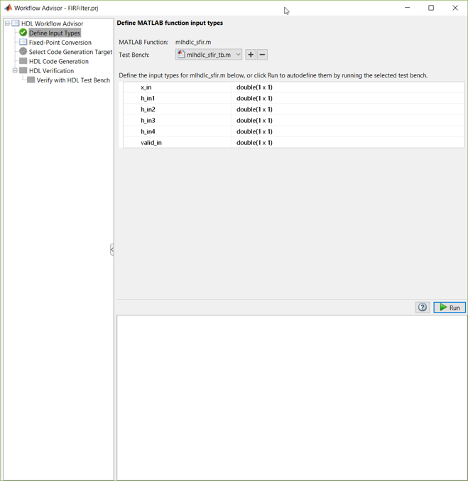 Note:
Note: If the automatically selected data types don’t match the intended data types, you can adjust the selected data types manually. However, the conversion to fixed-point representation will usually pick good data types regardless of the MATLAB function input types.
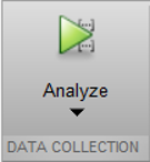
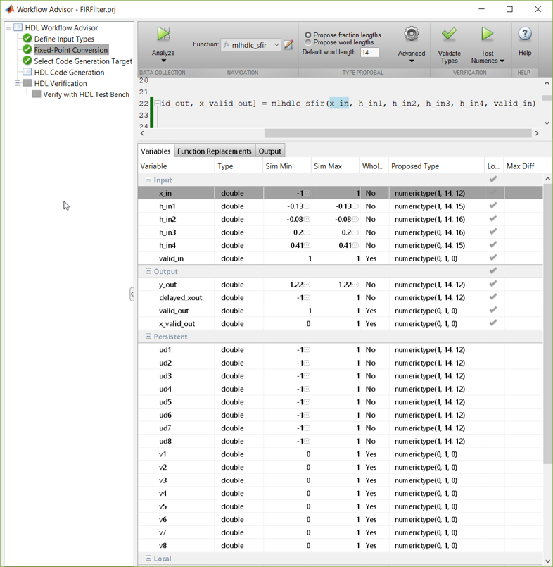
- Select the Fixed-Point Conversion page. This page’s default configuration will use the test bench defined previously to propose fixed-point ranges based on the data used. Click Analyze to run analysis using the test bench.
- After the analysis completes, click Validate Types to confirm the proposed data types. Review the selected data types to confirm they are sufficient for the design.
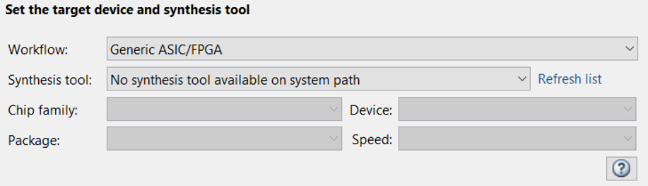
- In the Select Code Generation Target page, ensure that Workflow is set to Generic ASIC/FPGA. This setting allows generation of target independent VHDL or Verilog.
- Switch to the HDL Code Generation page to configure the actual HDL code formatting and generation.
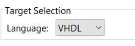
a. On the Target tab, set the Language to VHDL. LabVIEW FPGA cannot import Verilog without first creating a netlist.
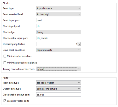
b. On the Clocks & Ports tab, ensure that the Clock edge is set to Rising, the Input data type is set to std_logic_vector, and that the Scalarize vector ports option is selected. LabVIEW supports only top-level ports of std_logic and std_logic_vector data types and does not support arrays.
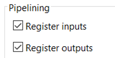
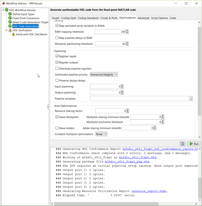
c. On the Optimizations tab check both Register inputs and register outputs to ensure that inputs and outputs are registered, which helps designs to integrate more easily when you pipeline the design.
- Finally, click the Run button to perform the final HDL Code Generation. Note the console output and ensure that the generation completes without error.
 Note:
Note: The HDL Verification steps are optional. For more information on these pages, refer to the official documentation.
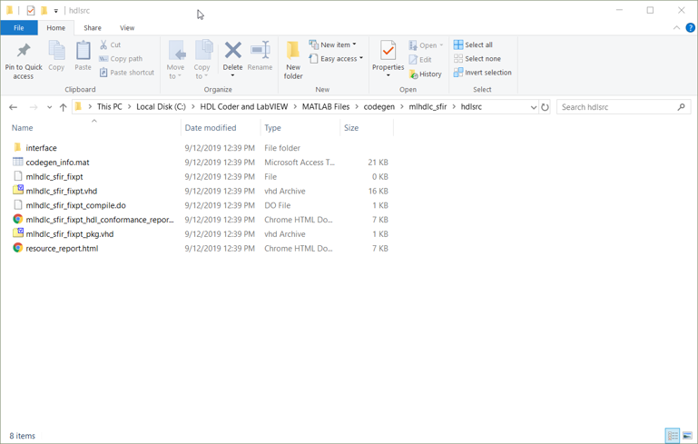
- Exit the Workflow Advisor. In the directory the project was created in, there should now be a codegen directory. The generated *.vhd files can be found in the hdlsrc directory for the design. For example: C:\HDL Coder and LabVIEW\MATLAB Files\codegen\mlhdlc_sfir\hdlsrc.