Prerequisites
Before starting this tutorial, NI recommends reviewing the information in MATLAB, Simulink, and LabVIEW FPGA: Importing HDL Coder into LabVIEW FPGA Designs.
Note: This tutorial assumes familiarity with Simulink. For more information and examples of Simulink designs, refer to the official documentation and the MathWorks website.
Install the following software with the specified version. Other versions may also work but the UI might be different.
- MATLAB R2019a
- Simulink R2019a
- Fixed-Point Designer™
- MATLAB Coder™
- HDL Coder
- Signal Processing Toolbox™ recommended
- DSP System Toolbox™ recommended
- HDL Verifier™ recommended
Modifying a Simulink Model
- Create a new folder for storing the Simulink model and HDL Coder exports.
- Launch MATLAB.
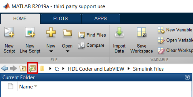
- In MATLAB, browse to the folder created in step 1 using the Browse for Folder button.
- In the Command Window, run the following command to copy the sample Simulink model design to the current directory:
copyfile(fullfile(fullfile(matlabroot,'toolbox','hdlcoder',... 'hdlcoderdemos'),'sfir_fixed.slx'),pwd);
After doing so, confirm the model appears in the current folder: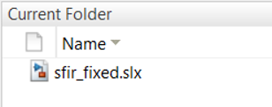
- Modify the FIR filter to add Valid In and Valid Out interface signals which will be used to interface with the LabVIEW FPGA VI. Open sfir_fixed.slx to view the top-level system. This system includes several inputs for testing the model and a subsystem which contains the actual FIR design.
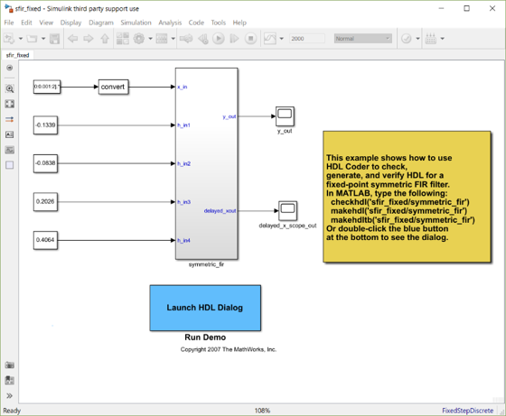
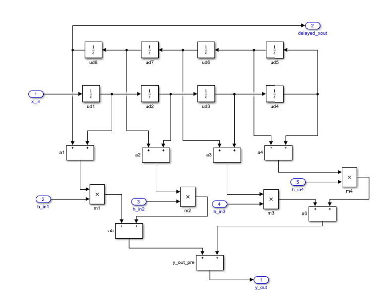
- Double-click the symmetric_fir block to open the subsystem which will be exported via HDL Coder. The initial design should look as below.
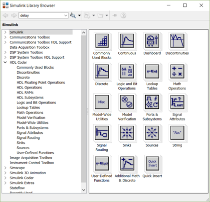
- Open the Simulink Library Browser by selecting View >> Library Browser or using the Ctrl + Shift + L shortcut.
- Navigate to HDL Coder >> Commonly Used Blocks in the Library Browser.
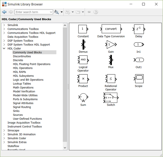
- Place an In1 block and two Out1 blocks in the FIR subsystem. These will be the additional inputs and outputs.
- Label the input as valid_in, and the two outputs as valid_out and x_valid_out.

- From the HDL Coder >> Commonly Used Blocks section of the Library Browser, place a Delay block.

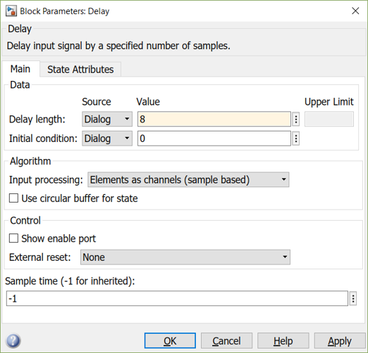
- Double-click the Delay block to configure it. In the Block Parameters: Delaywindow, set the Initial condition to 0 and the Delay length to 8 in order to match the delay of the delayed_xout output. Click OK.
- Connect the delay, input, and outputs as shown below. The valid_out signal represents when the output of the FIR filter is valid, and by design will output every cycle when there is a valid input. The x_valid_output has an 8-cycle delay to account for the delay on the delayed_xout signal.
 Note:
Note: This method of handling the valid signals assumes that once valid data is given to the filter, every subsequent cycle valid input is available until the filtering is complete. If cycles of invalid data will occur between cycles of valid data, NI recommends using handshaking such as AXI in the top-level interface.
- Save the Simulink model.
- The subsystem inputs and outputs are configured to inherit data types from their inputs in the top-level system. To make sure HDL Coder recognizes the data types correctly, stimuli need to be provided for the subsystem. Click the Up to Parent button on the toolbar to navigate back to the top-level system.

- In the Library Browser, navigate to Simulink >> Commonly Used Blocks and place a Constant block

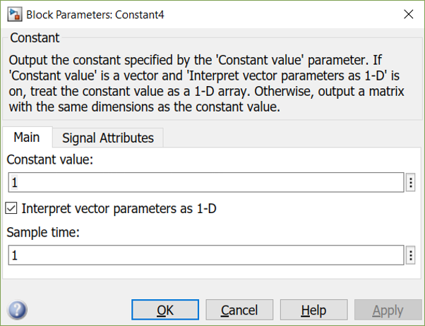
- Double-click the Constant block to configure it. In the Main tab, set the Constant value and Sample time to 1.
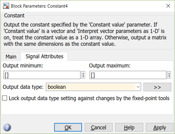
- In the Signal Attributes tab, set the Output data type to boolean. Click OK.
- From the Library Browser in the Simulink >> Commonly Used Blocks, place two Scope blocks.

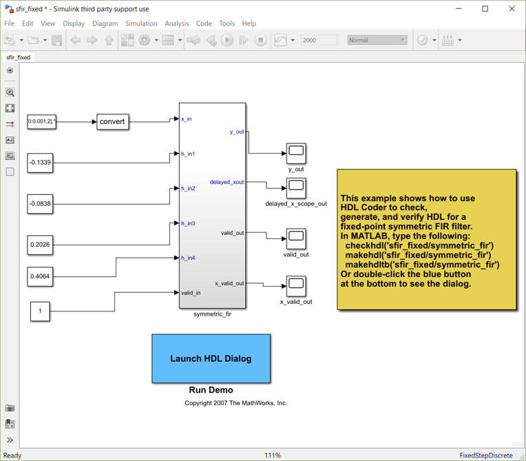
- Complete the top-level system as shown below.
- Save the model.
- To confirm that the system behaves as expected after the modifications, run the model by clicking the Run button in the toolbar.

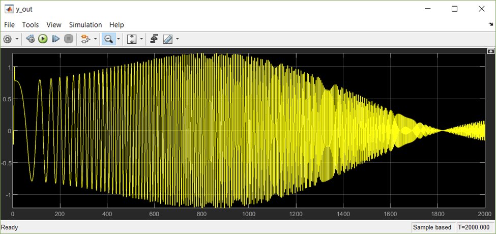
- Double-click the y_out scope to view the filtered signal.
 Note:
Note: You may have to zoom out to see the entire signal.
Generating VHDL Code with HDL Coder
After adding the required signals to interface with LabVIEW FPGA, complete the following steps to export the subsystem using HDL Coder.
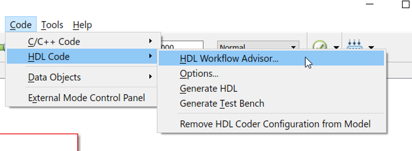
- In the MATLAB window where the Simulink system is open, select Code >> HDL Code >> HDL Workflow Advisor… in the menu bar.
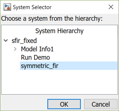
- When prompted, choose the symmetric_fir subsystem from the hierarchy. This defines that subsystem as the export target. Click OK.
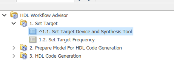
- You must complete several tasks before generating the HDL code. If the defaults are sufficient for each category, it’s possible to run through all items at once. However, for this tutorial several of the settings will be highlighted and each step will be run individually. Start by navigating to HDL Workflow Advisor >> 1. Set Target >> 1.1. Set Target Device and Synthesis Tool page.
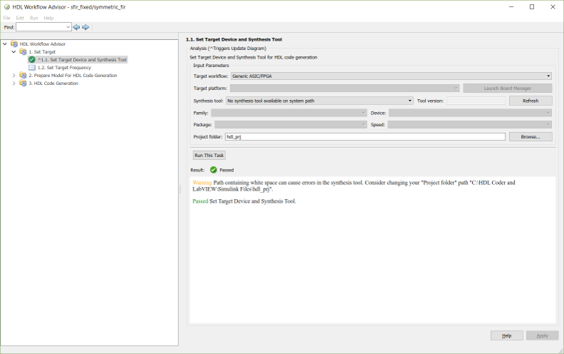
- Select Generic ASIC/FPGA for the Target workflow, and if desired modify the Project folder location. Click Run This Task to confirm the settings are valid.
- Navigate to the 1.2. Set Target Frequency page. This page allows HDL Coder to target the design for a specific frequency of clock and generate constraints.
Note: The IP Integration Node does not support the use of external constraints files. Constraints files can be used with Component-Level IP but may require modification to account for changes in the hierarchy. That is, the constraint paths may change when you integrate the constraints files into a larger design in the context of LabVIEW FPGA.
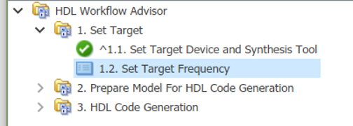
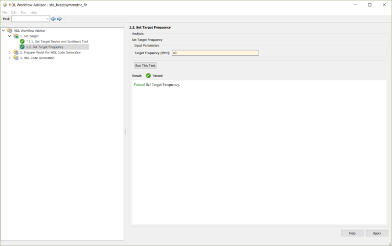
- Set the Target Frequency (MHz) to the clock speed of the Single-Cycle Timed Loop or clock source that the IP will be run in within LabVIEW FPGA. In this case, the default base clock of 40 MHz is used. Click Run This Task.
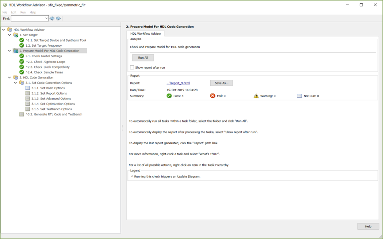
- Open the HDL Workflow Advisor >> 2. Prepare Model for HDL Coder Generation. These checks confirm that the selected system is compatible with HDL code generation and can be run all at once as no setting modifications are necessary. Click Run All to run through the required checks. For more information on what these checks do, refer to the official Simulink help documentation.
- Configure and confirm the code generation options in the HDL Workflow Advisor >> 3. HDL Code Generation >> 3.1. Set Code Generation Options >> 3.1.1. Set Basic Options page.
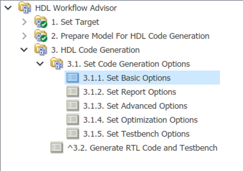
- Confirm that the Language is set to VHDL. LabVIEW FPGA cannot import Verilog without first creating a netlist.

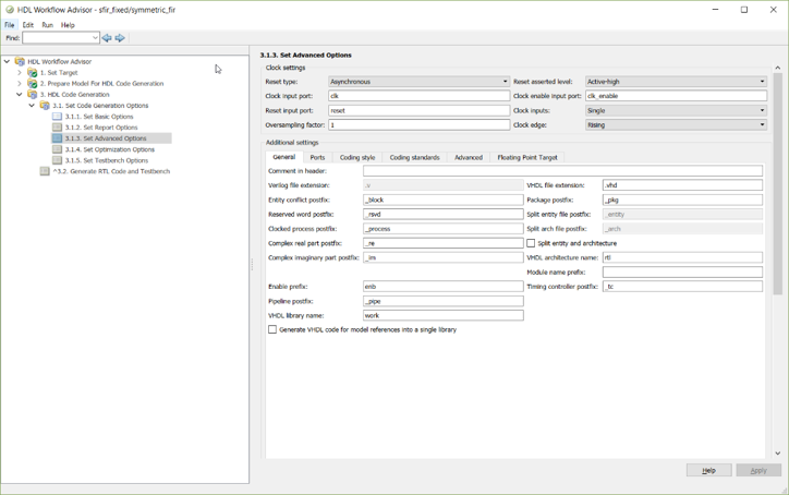
- Open the 3.1.3. Set Advanced Options page. Note the Reset type, Reset asserted level, and input port names.
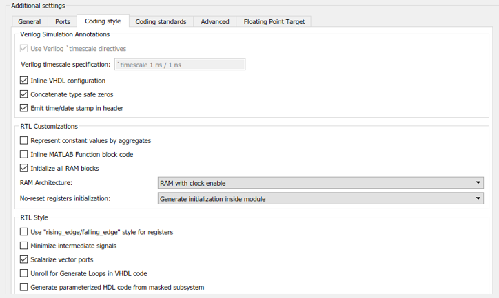
- Select the Coding style tab of the 3.1.3. Set Advanced Options page. Select Scalarize vector ports to ensure that all top-level ports are scalars. LabVIEW FPGA does not support arrays as top-level ports.
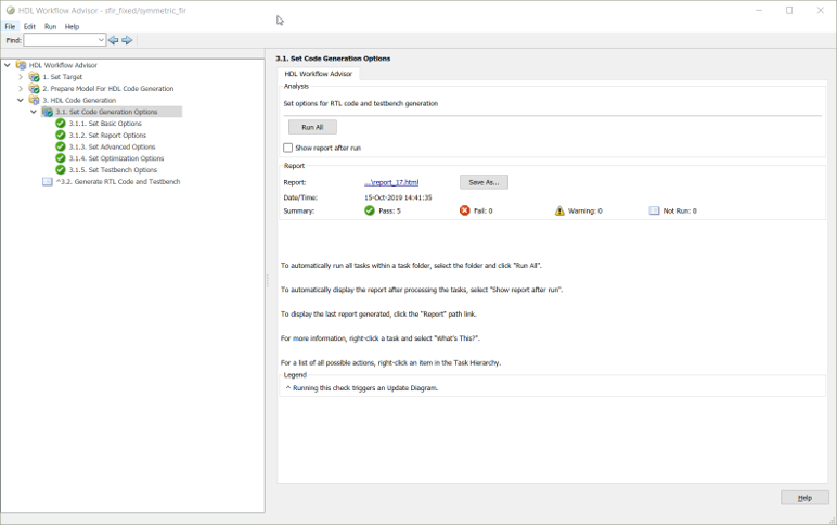
- The default options for the other pages should not require modification but it is recommended to review them. Navigate to the 3.1. Set Code Generation Options page and click Run All.
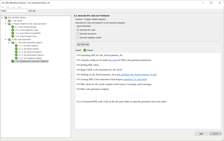
- Open the 3.2. Generate RTL Code and Testbench page and click Run This Task to generate the HDL code export.
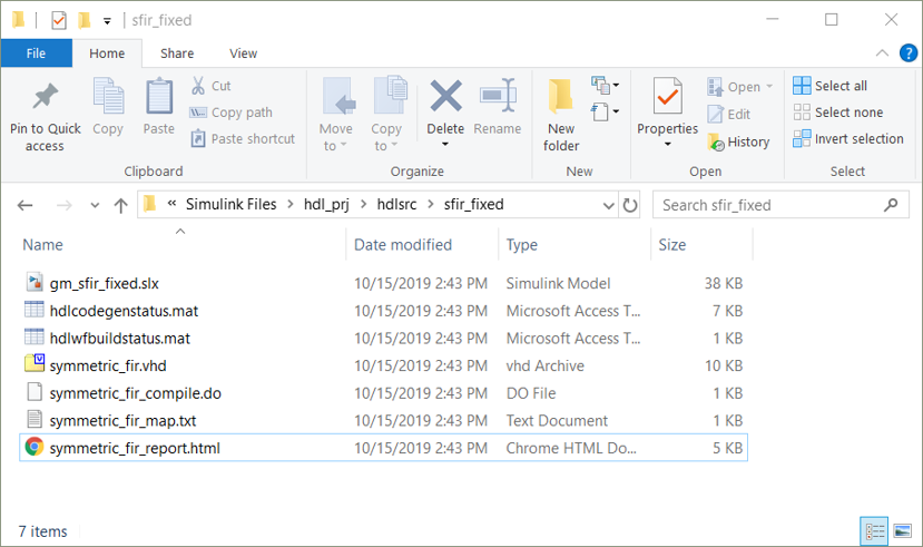
- Exit the Workflow Advisor. In the directory the project was created in, there should now be a hdl_prj directory assuming the project folder was not changed in step 4. The generated *.vhd files can be found in the directory for the design. For example: C:\HDL Coder and LabVIEW\Simulink Files\hdl_prj\hdlsrc\sfir_fixed\
