Configuring a Temperature Sweep Analysis in Multisim

Updated Nov 17, 2023

Environment

Software

  • Multisim

Multisim features a comprehensive suite of SPICE analyses for examining circuit behavior. These analyses range from the basic to sophisticated. Each analysis helps you to obtain valuable information such as the effects of component tolerances and sensitivities. For each analysis you need to set settings that will inform Multisim exactly what to analyze, and how.

Multisim simplifies the procedure for an advanced analysis by providing a configuration window. This abstracts away the complexities associated with SPICE syntax and configuration of an analysis. With this window you merely need to specify the parameter values and output nodes of interest.

This tutorial is part of the NI SPICE Analysis Fundamentals Series. Each tutorial in this series provides you with step-by-step instructions on how to configure and run the different SPICE analyses available in Multisim.powerful simulation and analysis while abstracting the complexity of SPICE syntax.
 

When you run a simulation in Multisim, all the elements of the circuit are assumed to be measured at the nominal temperature of 27°C. This temperature can be changed by customizing the SPICE options. However, using Temperature Sweep Analysis, you can quickly verify the operation of your circuit by simulating it at different temperatures. The effect is the same as simulating the circuit several times, once for each temperature. You control the temperature values by choosing start, stop and increment values.
 

When you configure a Temperature Sweep Analysis in Multisim, you can define the temperature values to be swept and the type of analysis  to be run at the various swept temperatures. There are three types of sweeps: DC Operating PointTransient Analysis , and AC Analysis


The assumptions depend on the selected analysis as follows:

  • DC Operating Point Analysis. AC sources are zeroed out, capacitors are open, inductors are shorted, digital components are treated as a large resistor to ground.
  • AC Analysis. Applied to an analog circuit, small-signal. Digital components are treated as large resistances to ground.
  • Transient Analysis. DC sources have constant values; AC sources have time-dependent values. Capacitors and inductors are represented by energy storage models. Numerical integration is used to calculate the quantity of energy transfer over an interval of time.
 

In order to simulate circuits at various temperatures, the components of the circuit must have variation in their values, however, you must have in mind that Temperature Sweep Analysis affects only components whose model includes temperature dependency. In this tutorial we will focus on resistors.
 

In Multisim, the resistance of a resistor instance is calculated using the following equation:

where:

R = The resistance of the resistor.

Ro = The resistance of the resistor at temperature To.

To = Nominal temperature = 27°C.

TC1 = First order temperature coefficient.

TC2 = Second order temperature coefficient.

T = Temperature of the resistor.
 

Before running a Temperature Sweep Analysis, you must specify the desired values for TC1 and/or TC2. The temperature coefficient is usually expressed in ppm/°C (parts per million per degree Centigrade) units.


Consider the common-emitter (CE) amplifier shown in Figure 1. This configuration offers a high gain, however the gain depends on the temperature and bias current. In this exercise you will vary the temperature of the emitter resistor (RE) to see its effect on the amplifier’s gain.
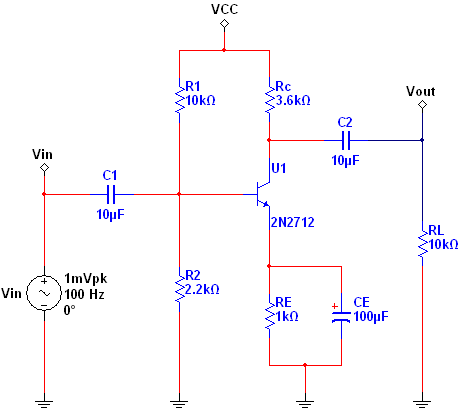

Figure 1. Common-emitter amplifier

Complete the following steps to configure and run a Temperature Sweep Analysis:

  1. Open circuit file ce_amplifier.ms11 located in the Downloads section.
  2. Open the Oscilloscope front panel and run the simulation. Observe the input and output waveforms. As mentioned before, this amplifier offers a high gain.
  3. Stop the simulation.
  4. Double-click resistor RE to open its properties.
  5. Select the Value tab.
  6. Enter a Temperature Coefficient (TC1) of 250 ppm/°C  (see Figure 2).

Figure 2. Specifying the Temperature Coefficient (TC1).
 

  1. Click OK to close this window.
  2. Select Simulate»Analyses»Temperature Sweep. The Temperature Sweep Analysis window opens. Table 1 describes the Analysis Parameters tab in detail.
 

Table 1. Parameters used in Temperature Sweep Analysis

Parameter

Meaning

Sweep Parameter

In this case you can only select the Temperature parameter. A brief description of the parameter appears in the Description field and the present value of the parameter is displayed in the Present Value field.

Sweep Variation Type

Dictates how to calculate the interval between the start and stop temperatures. Temperature Sweep Analysis plots the appropriate curves sequentially. The number of curves is dependent on the type of sweep as shown below:

  1. Decade: The number of curves is equal to the number of times the start value can be multiplied by ten before reaching the end value. 
  2. Linear: The number of curves is equal to the difference between the start and end values divided by the increment step size.
  3. Octave: The number of curves is equal to the number of times the start value can be doubled before reaching the end value.
  4. List: The number of curves is equal to the number of values entered in the Value List (items in the list must be separated by spaces, commas or semicolons).

Analysis to sweep

Select the analysis to sweep. There are four options:

  1. DC Operating Point
  2. AC Analysis
  3. Transient Analysis
  4. Nested Sweep

You can set the analysis parameters by clicking the Edit Analysis button.


Note: In SPICE, the command that performs a Temperature Analysis has the following form: .TEMP T1 <T2 … TN> Where .TEMP initializes a Temperature Analysis;  T1 is the first temperature at which the circuit is to be simulated,  TN is the Nth temperature at which the circuit is to be simulated. Note that these parameters are similar to those defined in Table 1.

  1. Configure the Analysis Parameters as shown in Figure 3.

Figure 3. Analysis parameters for the Temperature Sweep Analysis.
 

  1. Click on the Edit Analysis button. The Sweep of Transient Analysis window opens.
  2. Configure the Analysis Parameters as shown in the following figure:

Figure 4. Sweep of Transient Analysis window.
 

Refer to the Transient Analysis tutorial for more details on how to configure the Analysis Parameters tab.

  1. Click OK to close the Sweep of Transient Analysis window.
  2. Select the Output tab.
  3. Select the Variables in circuit list, select All variables from the drop-down list, and then highlight V(vout) from the list.
  4. Click the Add button to move the variable to the right side under Selected variables for analysis, as shown below.

Figure 5. Output variable for the Temperature Sweep Analysis.
 

  1. Click Simulate. The Grapher View window opens. Results are displayed in Figure 6.

Figure 6. Temperature Sweep Analysis results.


As you can see, as the temperature increases, the output of the CE amplifier decreases. Use the Cursors to obtain precise measurements. You can also perform nested sweeps, combining various levels of device/model parameter sweeps.