Gerber Properties
To begin generating the PCB files, the settings for each of the various file types will need to be established. The first files needed are the Gerber files which allow the manufacturer to create the basic artwork for each of the layers. From the menu:
-
Launch the Export setup window from the menu by selecting File > Export….
-
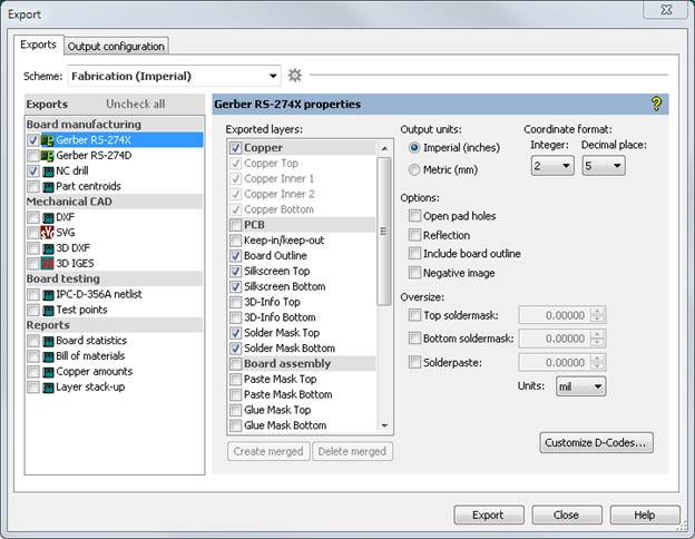
Ultiboard has default settings for different export schemes such as Fabrication or Fabrication and Assembly
-
To export Gerbers and Drill files select Fabrication from the drop down menu and the units system used by your board manufacturer

Figure 1 - Export Dialog Box
The RS-274X standard is preferred as it is the most current and widely used Gerber format and automatically assigns the D-code aperture setting whereas the RS-274D requires the manual setup of aperture settings. Aperture D-codes set the basic drawing tool sizes and styles used by the manufacturer to physically create the various layers of the PCB.
In the Gerber properties window, the following Available Layers will be automatically selected, you can add more layers to the export if needed.
-
Board Outline
-
All copper layers (Copper Top, Copper Inner 1, Copper Inner 2, Copper Bottom, etc…)
-
Drill (may be optional for quick turn PCB services using standard drill sizes)
-
Drill Symbols (may be optional for quick turn PCB services using standard drill sizes)
-
Silkscreen Top and Silkscreen Bottom (for single sided boards only the top silkscreen layer may be required)
-
Solder Mask Bottom and Solder Mask Top (may be optional for quick turn PCB services)
It is important to complete the following steps to finalize export:
-
In the Units section select Imperial (Mil)
-
In the Digits section, select integer 2 and decimal place 4
-
Oversize the Soldermask based on PCB manufacturer’s recommendations (some quick-turn PCB manufactures suggest over sizing the PCB mask to allow for adequate spacing around pads for the solder mask tolerances).
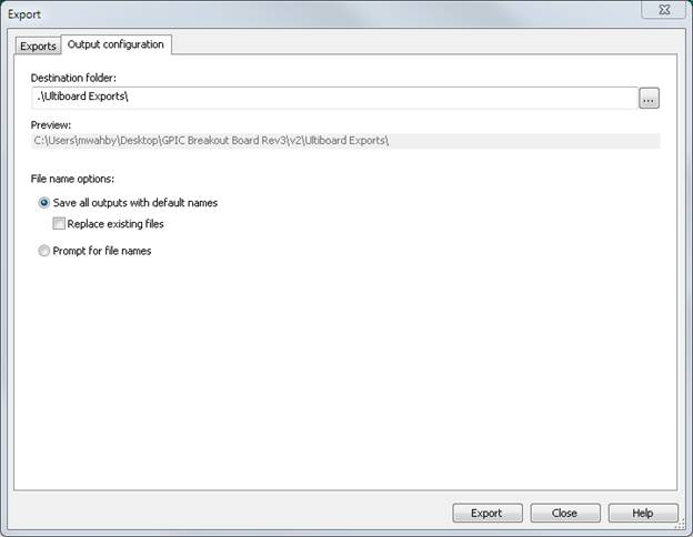
Now, go the the Output Configuration tab and this where you can define where all the Gerber and Drill files will be saved on your computer. By default it will be set to the same directory where your design file is saved.

Figure 2 - Export Dialog Box Output Configuration
Drill Tables
In any PCB, there are typically many holes that need to be drilled for things such as through-hole parts, vias and mounting holes. There are multiple files relating to the drilling of the holes in the PCB. The one essential in the creation of the PCB is the NC Drill file (NC = Numerically Controlled). The NC Drill export selection will create two files, a ‘.drl’ and ‘.rep’.
The rep is a report file listing a summary of the drill sizes and quantities. The drill sizes are associated with an individual drill bit (i.e. “tool”) so the tool numbers (“T#”) are shown as each individual sized hole. If the number of drill sizes can be kept to a minimum, the cost of the PCB will be reduced since it will take less time to switch between sizes when the PCB is being made.
The drl file shows the exact locations of each hole. It is sorted by the tool number tool number so the PCB manufacturer knows the size and location of all the holes for a specific drill bit size.
In addition, there are two Gerber files that are related to PCB drilling. The Drill and Drill Symbols are created when the Gerber RS-274X is selected and subsequently these files are used in documentation such as the assembly drawing to verify all hole sizes and drill locations are correct.
The Drill Gerber file shows round images at each hole with the radius of the image the same as the hole radius. When viewing this layer, the user can observe the hole sizes, locations and relations to other locations on the PCB.
The Drill Symbols Gerber file has symbols shown for each tool. For example, if there are 5 different hole sizes needed for drilling into the PCB, there will be 5 different symbols on this Gerber layer.