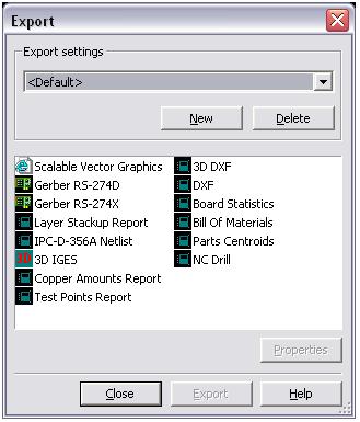
The Export dialog box is a simplified dialog box that you can use to establish the different parameters required by different manufacturers for the final file export.
This tutorial uses a shipping example to showcase the export process.
- Select File >> Open Samples.
- Select Intl4lRouted.ewprj.
- Click on the Open button.
You are now ready to view the export dialog box.
- Choose File»Export. The Export dialog box appears as seen in Figure 1 below.
You can see in the dialog box the various types of formats and reports that can be exported from NI Ultiboard for manufacturing purposes. This tutorial focuses primarily on the Gerber RS274X options, as this is one of the most common outputs for manufacturing purposes.

Figure 1. Export Dialog Box
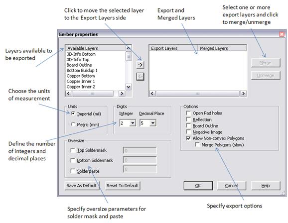
With the Gerber properties (RS274X or RS274D) dialog box, you can select the layers to be exported, the number of digits in numerals, and the kind of measurements.
- In the Export dialog box select Gerber RS274X and click the Properties button.
In Figure 2 below, you can see the various parameters that can be set to configure your Gerber file export.

Figure 2. Gerber File Export
As can be seen in the figure above, there are a number of different parameters that must be set to properly export your design to the Gerber format. In Table 1 below you can see a description for each export option.
Table 1. Gerber File Parameters
| Option | What Is This Setting For? |
| Available Layers | Set the layers of the design that are to be exported. |
| Units | Set or change the measurement unit. There are two options,
either metric (mm) or imperial (mil). |
| Digits | Set the number of digits of precision for board measurements. |
| Oversize | Top Soldermask | Add incremental size to the soldermask on the top layer to
increase the real-estate available to solder SMD parts. |
Bottom
Soldermask | Add incremental size to the soldermask on the bottom layer to
increase the real-estate available to solder SMD parts. |
| Solderpaste | Add incremental size to the solderpaste layer. |
| Options | Open Pad Holes | Open up the pad holes on the design (a requirement by some
manufacturers) |
| Reflection | Set a mirror image of the board design. |
| Board Outline | Include the board outline on each exported Gerber file layer. |
| Negative Image | Invert all the colors on the board. |
Allow
Nonconvex
Polygon | Check this box if the design contains complex polygons. |
| Merge Polygons | Merging of the polygons is a requirement by some manufacturers. |
- To select the layers to export to Gerber format, you can left-click on the name of each layer in the Available Layers selection box. To select multiple layers at once, hold down the <CTRL> key while selecting.
The following are typical Gerber files needed to produce the board:
- All copper layers
- Soldermask Top/Bottom
- Silkscreen Top/Bottom
- Board Outline
Once you have selected all of the necessary layers, click the right arrow (highlighted in red in Figure 3 below), to add the selection to the Export Layers list.
With the layers selected (and any other option set, such as units, digits, options, oversize, and so on) you are ready to export the Gerber files.
Click on the OK button to save the settings and exit the properties dialog box.
- To finally export the various layers of your design, click on the Export button in the export dialog box (as seen in Figure 1).
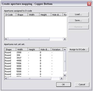
Ultiboard directs you to the Create aperture mapping dialog box (Figure 4). For Gerber RS274X files, there is no need to edit the aperture settings as they are automatically set by the export process.

Figure 4. Aperture Mappings
- Click on the OK button to finalize the export.
- Ultiboard directs you to save the exported gerber file. Select a destination folder and click on the Save button to finalize the location of the export.
Ultiboard now cycles through all the layers, and allows you to set the aperture settings and file locations for each layer of the design. This means repeating Steps 8 and 9 for each layer.
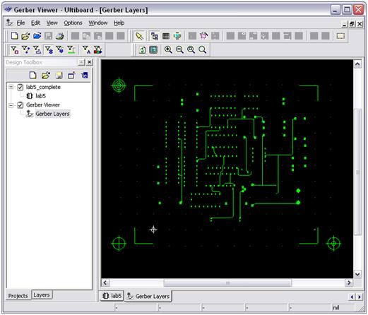
Ultiboard includes a built-in Gerber Viewer that you can use to verify the production files created.
- Simply go to File»Open and select a generated Gerber files.
- Click on the Open button.
You can now view the exact file that the manufacturer views, as can be seen in Figure 5 below.

Figure 5. Gerber Viewer