Setting up the RT Target as a Modbus Slave IO Server
- Inside of the LabVIEW project, right-click on your RT Target and Select New » IO Server. This will pop up a Create New I/O Server window. Select Modbus Slave and hit Continue. This will pop up a Configure Modbus Slave I/O Server window as seen in figure 1 below.
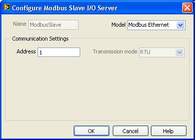
Figure 1. Configure Modbus Slave I/O Server Window
- Set the Model field in the Configure Modbus Slave I/O Server window to Modbus Ethernet, set the desired Modbus Address. It should look similar to the configuration in figure 1. Select OK. This will add a .lvlib to your project under your RT Target.
- Expand the .lvlib and you will see the Modbus Slave IO Server. Rename this if you want. Note: Currently, if you rename the IO Server after creating shared variables bound through this IO Server, your binding will become incorrect and you will need to updated the binding paths manually.
- Right click on the Library, select Save and save the .lvlib to disk. Note: Currently, if you rename the .lvlib after creating shared variables bound through this .lvlib, your binding will become incorrect and you will need to updated the binding paths manually.
- Now that your IO Server is set up, you need to create your shared variables that are bound to Modbus registers. Right click on the .lvlib and select New » Variable. This will pop up a Shared Variable Properties window.
- Set the shared variable up how you want and then place a check box in Bind to Source field and select Browse. This will pop up a Select Source Item window as seen in figure 2 below.
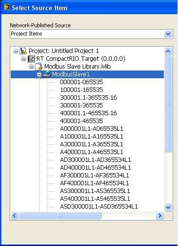
Figure 2. Select Source Item Window
- In the Select Source Item window, expand down through the project until you get through the IO Server. This will give you access to the Modbus registers and should look similar to figure 2 above. Select the desired Modbus register range for the shared variable and select OK. This will fill in Path field with your RT Target name\.lvlib name\IO Server name\Default Modbus Register. By default, the Modbus register will always be the first register in the selected range even if that specific register has already been used. An example of this default that may need to be changed is shown in figure 3 below. You will need to manually change the Modbus register to the desired register in the Path field. Note: Be careful to not use a specific register more than once as this will cause issues. If you need more information about the Modbus register definitions, see the LabVIEW help topic "Using Modbus I/O Servers".
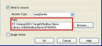
Figure 3. Default Binding Path for a Shared Variable Bound to a Modbus Register (F400001-F465534 range) in the Shared Variable Properties Window
- Select OK. This will add the shared variable to the project
- Create as many variables as desired and make sure to edit the Modbus register in the Path field so no two shared variables use the same register. When you have added all your shared variables, save everything. Then go to Tools » Shared Variable » Variable Manager. This will pop up the Variable Manger window.
- If you have not added your RT Target to the Variable Manager do so by right clicking on RT Systems and select Add RT System. Enter the IP Address and select OK. This will add your RT system to the Variable Manager. Make sure that you don't have any Modbus Slaves deployed to the RT Target at the same Modbus address as the one you just created. If you deploy two or more Modbus Slave IO Servers at the same Modbus address, you will run into issues. You will need to remove all Modbus Slave IO Servers at that specific Modbus address before you can deploy the library you just created. Do this by right clicking on the specific libraries and selecting Remove Process.
- In the LabVIEW project, right click on your newly created .lvlib and select Deploy.
- You should now be able to refresh the Variable Manager by selecting Action » Refresh and see your .lvlib deployed under your RT Target. You can then expand the .lvlib and drag the shared variables from under your RT Target into the Watched Variables window. You can then double click any variable you want and change the current value. If you already have a third party Modbus Server watching the RT Target, you should now be able to see any value changes in the shared variables. Figure 4 below gives an example of what the Variable Manager should look like.
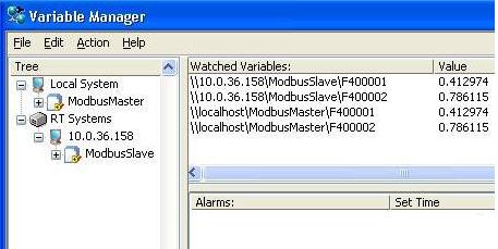
Figure 4. Variable Manager Window
Using these shared variables in writing your RT application is no different than how you normally use them in RT. You can add or remove variables as needed. Just remember that if you make any changes to the IO Server Name or the .lvlib name, you will need to manually update the Path of the bound shared variables before deploying. Also remember to remove any Modbus Slave IO Servers at the same Modbus Address that are already deployed to the RT Target through the variable manager before re-deploying.
Setting Up a Windows Modbus IO Server to Read the RT Target
Note: This portion of the tutorial is only to confirm that your shared variables are working through Modbus correctly. You could also do this to use the additional functionality of the LabVIEW DSC Module. Otherwise, to use the Modbus shared variables in LabVIEW for Windows, simply drag the shared variable from under the RT Target into your LabVIEW for Windows VI and program as is normally recommended with shared variables.
- Right click on My Computer in the LabVIEW project and Select New » IO Server. This will pop up a Create New I/O Server window. Select Modbus and hit Continue. This will pop up a Configure Modbus I/O Server window.
- Set the Model field in the Configure Modbus I/O Server window to Modbus Ethernet and set the desired Modbus address. In this example, set the Modbus address to the address set in the Modbus Slave IO Server (RT Target).
- Select the Advanced... button. This will pop up an Advanced Attribute Settings window shown in Figure 5. Check the First word low in 32-bit data types option. This is selected because data will be coming in from your RT Target in big endian and selecting this option will take that into account when trying to read that data. Select OK in the Advanced Attribute Settings window.
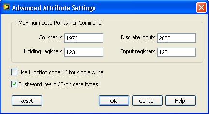
Figure 5. Advanced Attribute Settings Window
- Enter the IP Address of the device you are going to be reading from. In this case, the RT Target that is configured with your Modbus Slave IO Server. The settings should be similar to Figure 6 below. Select OK. This will add a .lvlib to your project under My Computer.
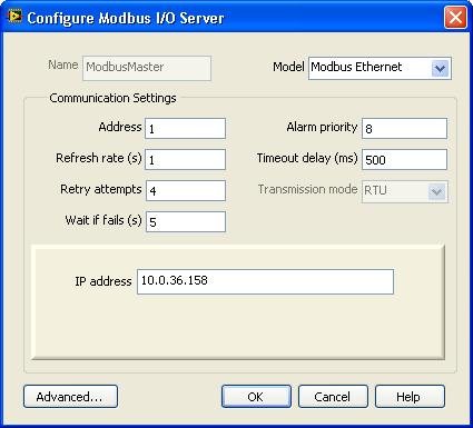
Figure 6. Configure Modbus I/O Server Window
- Expand the .lvlib and you will see the Modbus Slave IO Server. Rename this if you want. Note: Currently, if you rename the IO Server after creating shared variables bound through this IO Server, your binding will become incorrect and you will need to updated the binding paths manually.
- Right click on the Library, select Save and save the .lvlib to disk. Note: Currently, if you rename the .lvlib after creating shared variables bound through this .lvlib, your binding will become incorrect and you will need to updated the binding paths manually.
- Set up your shared variables in the same manner as on the RT Target being sure to bind the shared variables through My Computer. Also, make sure to bind the shared variables to the same Modbus registers as the RT Target Variables. It will be a one to one ratio meaning the shared variable bound to a specific Modbus register on the RT Target will need to have a shared variable bound through the Windows Modbus IO Server to that same specific Modbus register to be read.
- Deploy the .lvlib in the same manner as described above. The .lvlib will show under Local System in the Variable Manager.
Now, the deployed shared variables under My Computer should be reading the same values as the relating RT Target shared variables via the Modbus protocol. Again, relating shared variables means shared variables bound to the same Modbus register with one shared variable being bound through the RT Target and the other shared variable being bound through My Computer.