Additional Information
Assume the following FPGA VI:
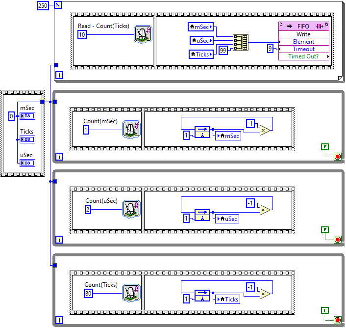
In this code, three square waveforms are generated and read in parallel:
- Firstly, the outputs are re-set to 0.
- Then three data generation loops start executing, all beginning with an Loop Timer Express VI. The first one is using the mSec setting, the second one the uSec setting, and the last one is using the Ticks counter.
- After each Loop Timer has returned, each respective output is set to 1.
- On the next loop iteration, the counters wait for the defined period(s) of time, afterwards -1 is written to the outputs.
- This repeats.
- In parallel, all outputs are read at a high rate right from the beginning. The values read are transferred to a PC using a FIFO.
The following chart is created from the values read from the FIFO:
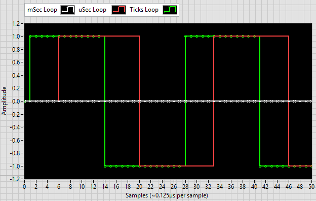
It can be recognized that all three outputs have a delay before switching from the initial
0 to
±1. These initial delays vary:
- For the loop using the Loop Timer Express VI set to use Ticks (green line with circles) it is just one sample. This is because the acquisition loop starts roughly at the same time as the generation loop.
- The Loop Timer Express VI set to use uSec (plain red line) has a delay of up to one microsecond. That's the maximum duration the timer needs to wait for an edge of the clock signal.
- For the loop using the Loop Timer Express VI set to use mSec (white marked line with x's), the first transition to +1 is out of scope of this diagram. It happens after 1 ms maximum, however the diagram's x range covers only about 0.06 ms.