Solution
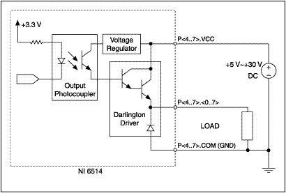
The NI-6512/6514/6516/6518 devices offer digital output lines for sourcing current. The following block diagram shows how the output line is switched and how to connect a load.

Notice that the connection between PX.X and Vcc is made by a Darlington Driver. This driver chip will introduce a voltage drop between its connecting terminals. The drop is not constant and is a function of the current being sourced. The voltage drop will not exceed the following specifications:
| Output Current | Max Voltage Drop |
| 100 mA | 1.8 V |
| 225 mA | 1.9 V |
| 350 mA | 2.0 V |
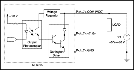
The NI-6513/6515/6517/6519 devices offer digital output lines for sinking current. The following block diagram shows how the output line is switched and how to connect a load.

Notice that the connection between PX.X and Ground is made by another Darlington Driver. This is a different chip but will also introduce a voltage drop between its connecting terminals based on the current being accepted. The voltage drop will not exceed the following specifications:
| Output Current | Max Voltage Drop |
| 100 mA | 1.1 V |
| 200 mA | 1.3 V |
| 350 mA | 1.6 V |