Solution
Some applications require a higher voltage output than one SMU can supply. It is possible to cascade, or connect in series, channel 1 of multiple SMUs to increase the possible voltage output. See the related links section for discussion of cascading NI Power Supplies and SMUs.
When cascading SMUs, you can still take advantage of the remote sensing feature to ensure that the increased voltage is accurately seen at the DUT. However, the lead connections will be different than those that are made when using a single SMU.
Remote Sense
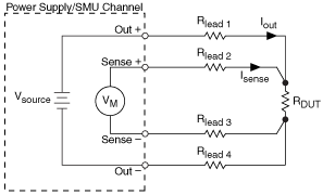
Measurements made using remote sense traditionally require 4-wire connections from the SMU to the DUT, seen in the image below. In a remote sense configuration, one set of leads carries the output current, while another set of high input impedance leads is used to measure voltage directly at the DUT terminals, as illustrated in Figure 1. The SMU will maintain the desired output voltage at the Sense leads by increasing the voltage at the output to compensate for voltage drops due to lead resistance.
Remote sense can be enabled or disabled using the niDCPower Configure Sense VI on a per output basis for channels that support this feature.

Figure 1: Remote Sense connections for one SMU
Remote Sense Connections for Cascaded SMUs
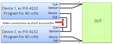
Measurements made using remote sense with cascaded SMUs will still require 4-wire connections for each SMU. However, the connections will be made as seen in Figure 2.

Figure 2. Remote Sense Connections when using two SMUs, here two PXI-4132s.
Considerations for wiring remote sense:
- No matter your application or the number of devices you are working with, it is always a good practice to ensure that all of your wires are as short as possible. This will minimize voltage losses due to lead resistance. Remote Sense forces the point where the sense leads are connected to be the specified voltage. This means that the Out+ and Out- terminals will continue to increase their voltage outputs until the difference due to lead resistance is made up. If voltage loss across the leads is significant and the configured voltage output is near the upper limits of the device, this can result in a voltage at the load that is less than the requested level.
- Ideally, the sense leads should be connected as close to the DUT terminals as possible, since it is at these leads that the voltage is forced to the correct value.
- When cascading SMUs to increase the voltage output, the Out+ of Device 2 is jumped or tied to the Out– of Device 1 as illustrated in Figure 2. In this same way, the Sense+ of Device 2 is jumped to Sense– of Device 1. However, in order for remote sense to measure the voltage being supplied by the Out+ and Out– terminals of that device, the sense jumper must be tied to the output jumper, as seen in Figure 2.
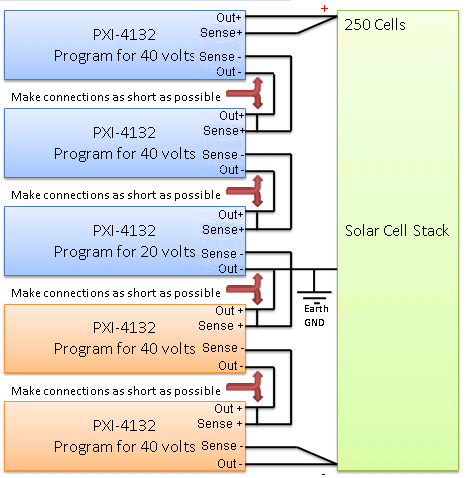
- When cascading more than two SMUs, you will need to make sure that the total voltage being supplied remains within the Isolation or Channel-to-Ground Specification for that model of SMU. For instance, the voltage supplied by cascaded NI PXI-4130 SMUs must remain within ±60V from Ground. For the NI PXI-4132, the voltage must be within ±150V from ground. An example of how to connect the remote sense leads and how to ground the cascaded SMUs can be seen in Figure 3 below.
- Additionally, if you cascade more than two SMUs, ensure that the connection setup between modules is consistent throughout your system. In Figure 3, notice that the length between the sense lines and the voltage lines is in the same location for every module.

Figure 3: Remote Sense and Ground connections when cascading more than two SMUs