Solution
The NI 73xx motion controllers contain a PID controller that allows you to use position and velocity feedback to adjust your control signals. This feedback reads any analog voltage or pulse train signal from an encoder indicating the position and speed of the motor. The controller compares its control signals with the feedback signals to verify if the motor follows the commands. The difference between these values is called following error.
Why does my application report that the following error has been exceeded when I make a move?There is an adjustable limit allowed for the tracking error during a movement. When the limit is exceeded, the error condition is created by reporting a failure in this limit. The tracking error condition can be caused by any combination of mechanical defects, improper inputs / outputs and / or damage to the control loop. Error tracking conditions can be difficult to correct, here are the most common causes:
- Cause 1: Incorrectly load the encoder resolution.
To increase the accuracy of feedback, NI motion controllers read each flank of the feedback signal from the encoder. With a quadrature encoder, this result is on four flanks (increasing and decreasing in lines A and B) for each quadrature pulse. So, if your quadrature encoder has a value of 2000 quadrature pulses per revolution, the controller actually read 8000 flanks per revolution and each of those is considered an account. When the input "Encoder counts per revolution" is set to MAX, this value is a common error for the physical resolution of the encoder. That property needs to maintain the corresponding number of accounts read by the controller, which is four times the resolution.
- Cause 2: Command / feedback inverted wires
When an order is sent in a positive direction, does the feedback signal return a positive movement? If the feedback signal indicates a negative movement, either the polarity of the analog output of the motor or the phase (A, B) of the encoder has been reversed. Verify a correct connection to remedy this situation.
If the polarity of the encoder is reversed, you can reverse the polarity to MAX. To change the polarity of the encoders, select an axis where the problem is occurring and find the encoder input. The polarity of either A or B changes on the encoder label, but not both and the index is being used.
- Cause 3: Inadequate closed-loop tuning of servomotor
NI servo motor controllers are designed for use in a variety of applications, a PID control loop must be configured for use in each specific situation. A suitable tuning for the loop (parameters of Kp, Kd, Ki, etc.) in MAX is necessary to ensure that the motor will respond as expected. If the system responds to commands with vibrations or erratic movements, the control loop may be out of tuning. Considerations for tuning your movement system can be found in
understanding servo tune .
- Cause 4: try to control movements very fast
A high-speed movement requires a sensitivity of the movement system. High speed controls or accelerations regularly produce following error conditions, the state of the motor installation may be unable to reach the desired speed and acceleration. (Causes may be excessive friction, misaligned mechanical parts or insufficient torque in the motor ). It may be necessary to make adjustments to the mechanical installation or to try to control at a lower speed / acceleration.
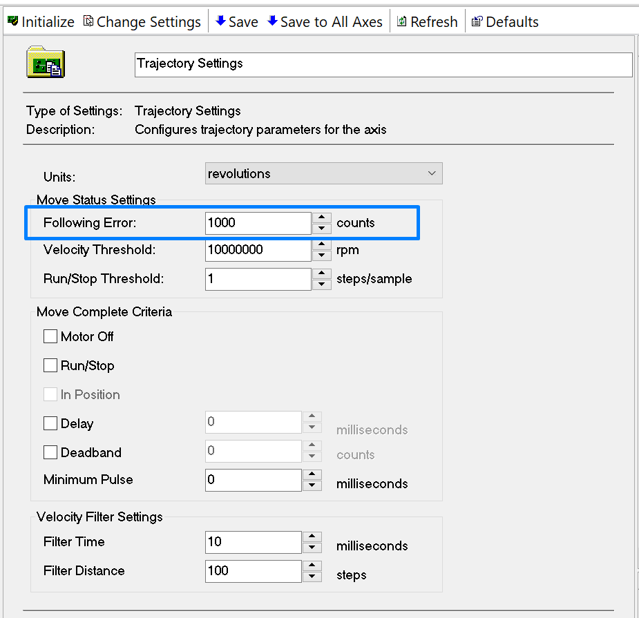
How can I change the maximum permissible following error?Under the Trajectory settings in MAX, the
Following Error can be loaded for each axis.

When movement commands use the screens in MAX "
1-D Interactive" or "
2-D Interactive", navigate to the
Advanced tab. In the
Advanced Data group, adjust the value labeled "
Following Error".
When using the FlexMotion API for LabVIEW, use the VI
Load Following Error.flx to load the number of allowed accounts.
When programming in C or Visual Basic use the function
flex_load_follow_err