Solution
Distortion constellations can result due to the following reasons:
- Uncompensated frequency offset between transmitter and receiver
- Poor signal to noise ratio (SNR)
- Clipping or DSP overflow due to signal power being too high
- Incorrect symbol or frame synchronization
Most of the NI USRP devices have internal DC offset correction mechanisms which automatically reduce the DC offset impairment. However if there is intentional DC content in your signal, the automatic DC offset correction mechanism may cause problems. The options below can help to remove the distortion from DC offset correction.
Method 1: Offsetting the carrier frequency from the local oscillator (LO) frequency on the receiver (RX) side.
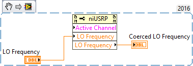
The DC offset correction mechanism works to reduce the feedthrough from the RX LO, but when the desired signal is also centered at the LO frequency, the DC content in the desired signal also gets affected. We can shift the LO away from the desired signal by offsetting the LO frequency from the carrier frequency. For example, if your carrier frequency is 2 GHz, you can set the LO frequency to 2.00009 GHz (offset of 90 kHz) and then set the carrier frequency to 2 GHz. The LO frequency can be set using the NI USRP property node for a specific channel.
Method 2: Changing the data clock rate.
Note: This is only supported on the NI USRP-2900 and USRP-2901 devices.
The automatic DC offset correction mechanisms are influenced by the data clock rate at which the device operates. As a rule of thumb, a higher data clock rate implies faster DC offset correction. Thus high data clock rates can detrimentally affect your desired signals if they have useful DC content in them. To mitigate the effect of the data clock rate on the DC offset correction, you can set it to a lower value. The data clock rate may be set using the Data Clock Rate niUSRP property node. The property must be set before the IQ rate is set. Do not forget to check the coerced IQ rate when you manually set the data clock rate as the list of possible IQ rates is data clock rate dependent.
Note: If you are using a single device to do both TX and RX, set the data clock rate to the same value on both the TX and RX sessions.