Changing Between Inputs and Outputs on DIO Lines on a Module in a CompactRIO

Updated Feb 11, 2022

Reported In

Hardware

  • CompactRIO Chassis
  • Digital I/O Device

Software

  • LabVIEW

Issue Details

I have a LabVIEW project using a CompactRIO with a digital input/output card inserted.  When I drag the card's line from the LabVIEW project window onto the block diagram, I can't seem to change the function from an input to an output using the block diagram access menu.

Solution

To change a digital line from an output to an input or vice versa, you will need to make the changes in the module settings.

Right click on the module under the cRIO in the LabVIEW project window and select Properties.


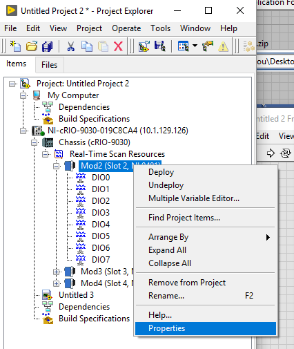
You should see the Module Properties window appear.  Select the Module Configuration option on the left side of the screen and you should see a section called Initial Line Direction.  By changing the input and output status of the lines, the line status will be changed when you drop the lines onto the block diagram. 


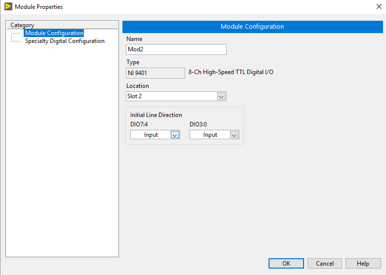
Depending on your device, you may be able to change each line independently or by group.

Additional Information

To make changes to the input and output of a module at run-time instead, you may use a property node to change the module I/O properties .