Solution
If you're acquiring data from a high impedance signal source, gain error could be affecting your voltage data.
NI DAQ devices have a high internal impedance to ensure that it captures the vast majority of the voltage drop, but extra precaution is advised when using high impedance signal sources.
Signal sources, such as transducers, have internal resistance and an output voltage source.
When the signal source's internal resistance value is large relative to the DAQ device's internal resistance, it skews the voltage drop that occurs within the DAQ device, misrepresenting the signal data.
The below diagrams show how this may occur when a DAQ device is connected to signal sources with varying impedance levels.
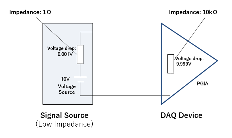
In above image, the DAQ device acquires data from a low impedance signal source (1Ω). In this case, this internal resistance causes a fairly insignificant voltage drop (0.001V) within the transducer, so most of the voltage drop occurs within the DAQ device (9.999V). As a result, the displayed voltage values are as expected.
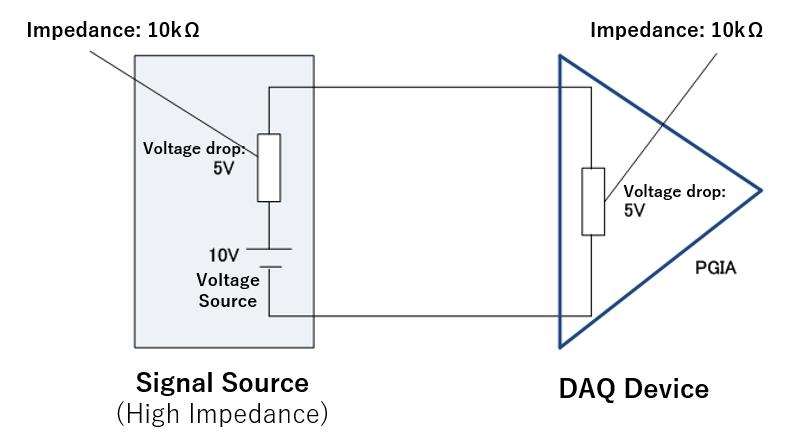
In the next image, the DAQ device acquires data from a high impedance signal source (10kΩ). This significant amount of internal resistance causes a partial voltage drop (5V) within the transducer. As a result, the voltage drop within the DAQ device is a mere 5V, and is not representative of the original signal. This type of error is known as a "gain error".
In NI M series DAQ devices, the input impedance is set to 10GΩ, significantly decreasing the possibility of gain error. Still, when acquiring data from a high impedance signal source, please consider that other factors, such as settling time, may also affect data acquisition.