First of all you create a separate DAQmx-task (consisting out of DAQmx Create Virtual Channel, DAQmx Start Trigger, DAQmx Start Task, DAQmx Stop Task and DAQmx Clear Task) for each counter you want to use. You specifiy for each task, which counter you want to use and on which Pin the signal should be output by setting a DAQmx channel Property Node. In this Property Node you choose
Counter Output>>Pulse>>Output Terminal and wire an I/O constant, in which you specify on wich PFI line the signal should be output to the property node. You find a table of all the outputs in the Pinout scheme of each module or in NI MAX (
Where to Find NI-DAQmx Device Pinouts or Pin Mappings). Below you find a screenshot how to setup the DAQmx Channel Property Node:

After you have set up each counter task, you have to create a so-called Frequency Output task, which is used as a trigger. The Frequency is Output is a internal digital pulse train on the chassis that can be used to trigger counters internally and without the use of an external signal. For more information about the Frequency Output Signal, please refer to the following Knowledge Base:
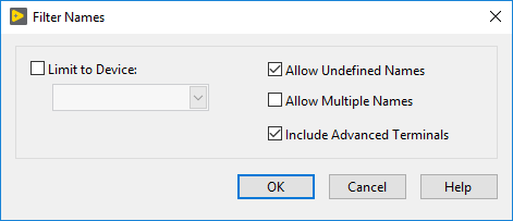
Output a Frequency Signal Without a Counter in NI-DAQmxTo use the Frequency Output you have to configure the I/O constants of the DAQmx Start Trigger VI in order to display the Frequency Output. For this you right-click on the I/O constant wired to the source input of the DAQmx Start Trigger VI and choose
I/O Name Filtering from the context menu. In this menu you activate
Include Advanced Terminals and now the I/O constant can display the Frequency Output, which you choose as your trigger source.:

You have now to create the Trigger Task. The Frequency Output task should look like this:

The I/O constant linked to the DAQmx Channel Property Node should be blank, because you do not need to output the signal via a pin of a module.
Afterwards you set the correct execution order by using the error lines. Here you should keep in mind that the counter output tasks must start prior to the Frequency Output task, because the counter tasks are going to start only after the trigger is send by the Frequency Output task. Overall the code should look similar to this (of course the settings for the high and low time and the initial delay of each Counter Output can be adjusted):

Additional Information
The above shown code is also attached as the VI
Counter Outputs Synchronized by Frequency Out below
You can also use an Analog Input task to trigger the Counter Output, which is described in the example program
Synchronizing Two Counter Tasks Using LabVIEW With NI-DAQmx