Additional Information
There are mainly two architectures for transmitting and receiving RF signals: heterodyne and homodyne.
In the RF system, the receiver requires more complex structure than the transmitter, so let's look at the receiver.
The goal of both methods is to convert the RF signal into a baseband IQ signal.
1. Heterodyne Receiver
Generally, a heterodyne receiver has the structure shown in the figure 3 below. Where w is the angular frequency. The frequency of the mixer is included according to the following equation.
Angular Frequency (w) =
2*
pi*
Oscillator's Frequency (f)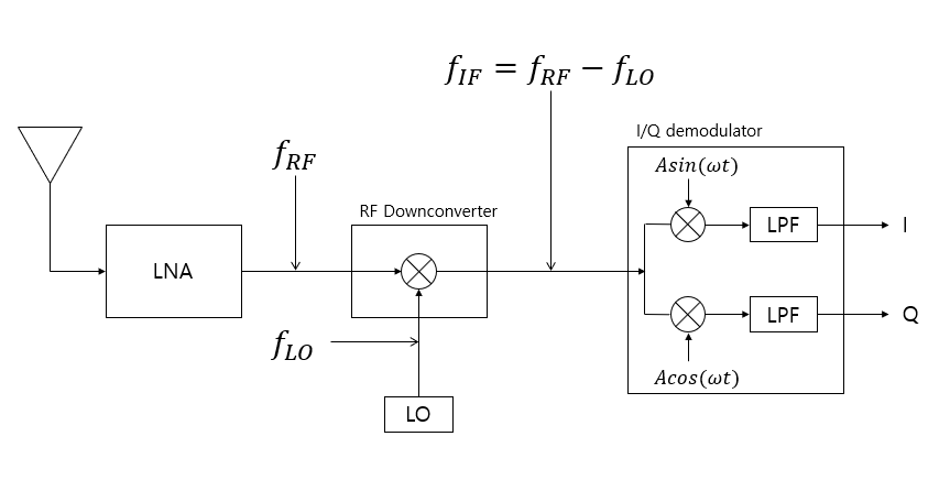
Figure 3. Heterodyne Structure
There is a stage called a IF, which acts as a buffer in a kind of frequency band conversion. After this process, the IF band signal is passed to the IQ demodulator circuit and demodulated into the IQ signal.
In a heterodyne receiver, it has one or more RF downconverter circuitry. If the IF signal stage is more than two stages, this is sometimes called a super heterodyne receiver. Between the IF stages, a BPF is required because the unintended RF signals from the mixer must be removed.
2. Homodyne Receiver
In homodyne receiver, it does not require any mixers at RF stage. The modulated RF signal is directly applied to I/Q demodulator which gives baseband signals out (I and Q) at zero IF. Therefore, this method may be referred to as a direct conversion or a zero IF method. The circuit configuration is simpler than a heterodyne receiver. See the figure below.
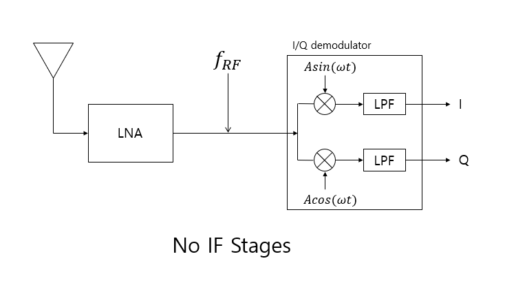
Figure 4. Homodyne Structure
The table below provides a simple comparison of heterodyne and homodyne modes. So, you can see which structure has more advantages in some aspects.
| RF Circuit Architecture | Heterodyne (including Super Heterodyne) | Homodyne (or Direct Conversion) |
|---|
| Intermediate Frequency (IF) | Exist | Don't exist |
|---|
| Filter Selectivity | Better | Good |
|---|
| System Sensitivity | Better | Good |
|---|
| System Stability | Better | Good |
|---|
| Circuit Module Reusability | Better | Good |
|---|
| Circuit Physical Size | Good | Better |
|---|
| Component Price | Good | Better |
|---|
| Power Consumption | Good | Better |
|---|
Because the two architectures are in a trade-off relationship to each other, the architecture that is applied depends on the application you want to use the RF receiver. Because of power consumption and price, direct conversion is mainly used in mobile communication terminal and wireless LAN. Especially in recent years, techniques have been introduced to complement the homodyne's drawbacks (eg, LO Leakage), so this architecture has been widely used. However, Heterodyne structures using IF are still used in applications requiring more stable performance.