Solution
To define the sampling rate of a specific device in LabVIEW FPGA, the maximum sampling rate of the device needs to be considered, which can be found in the module specifications. This maximum rate cannot be exceeded and LabVIEW will not be able to acquire the data any faster.
Most of the
NI C Series modules can use the following software architecture for setting predetermined sampling rates in the FPGA code. However, there are some modules which would require a different architecture, for example the Sound and Vibration modules.
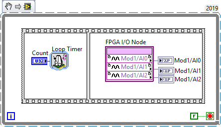 Note: This image is a LabVIEW snippet, which includes LabVIEW code that you can reuse in your project. To use a snippet, right-click the image, save it to your computer, and drag the file onto your LabVIEW block diagram.
The code above shows the minimum functions required to change the sampling rate of the module accessing its I/O with the
FPGA I/O Node. The
Loop Timer VI is used to define the time between each loop iteration, which is equal to the acquisition period. It can be calculated using the following equation:
T = 1/f, where T is the period, and f is acquisition frequency
The sequence structure is used to prevent the FPGA I/O Node from executing before the Loop Timer VI, thus enforcing the timing.