Solution
Unlike normal DAQmx programming, you cannot directly specify gauge factor and gauge resistance values to be used in the cRIO's scan engine or LabVIEW FPGA interface modes. Raw data obtained from either modes must be manually transformed into strain measurments.
Using Convert Strain Gauge Reading Function
The LabVIEW's Convert Strain Gauge Reading function in the scalar mode (available only at the RT target) allows you to perform the calculation on data acquired from the C modules.
To use the Convert Strain Gauge Reading function with voltage readings, you will need to change it to the scalar polymorphic type. To do this, you will need to right-click on Convert Strain Gauge Reading's icon>>Visible items>>Polymorphic VI selector>>Scalar. With the polymorphic VI now in the scalar mode you can wire up the required inputs and the VI will perfom the strain calculations and yield results in microstrain.
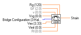
The value that the bridge-based NI 9218, 9219, 9235, 9236, 9237 returns is in ratiometric form (Volts/Volts), as can be seen from the LabVIEW Help file for each module. Therefore, use this function with caution as it assumes a plain voltage in its calculations. In fact as shown in figure 1, it performs this initial calculation first to turn a plain voltage (Vsg) into a ratiometric form (Vr):
Vr = (
Vsg –
Vinit) /
Vex
Where Vinit is an initial offset voltage and Vex is the excitation voltage.
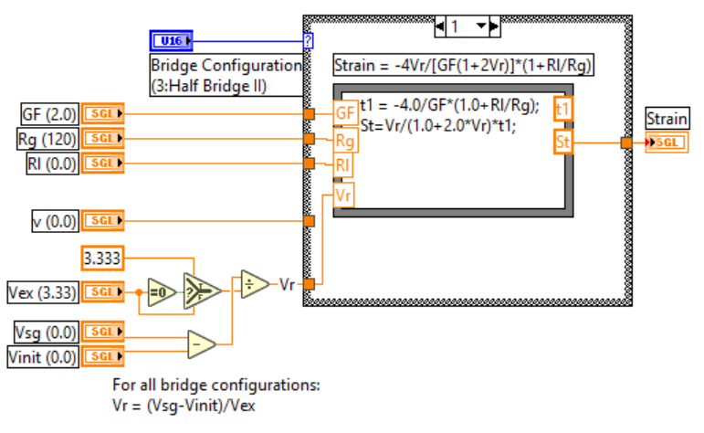
Figure 1, Internal calculations performed with the
Convert Strain Gauge Reading VI for the Quarter Bridge I and II configuration.
Because of this, you can either wire a constant of 1V to Vex to make this calculation independent of it, or you can refer to the Developer Zone Community example linked below to see an alternative conversion VI.
Manually Perform Calculations
As seen in the LabVIEW examples there is a second way to perform this calculations (In this case the NI 9237 example will be reviewed).
To find the module specific example of the NI 9237 go to Help>>Find Examples>>Compact RIO>>Module Specific>>NI 9237>>NI 9237 Getting Started.lvproj. In this project raw data is obtained by the FPGA module and then passed to the NI 9237 Getting Started (Host).vi by using a DMA FIFO. This VI performs the signal conditioning by first computing the offset measurment (offset nulling) and next performing a shunt calibration.
Finally, already processed data is then transformed into strain measurments at the Ratio to Microstrain (SubVI).vi, notice that the applied formula conversion depends on the bridge configuration. For example, the Quarter Bridge Case I and II are calculated using math Vi's as shown in figure 2.
Figure 2. Ratio to microstrain conversion for the Quarter Bridge I and II configuration.
Both approaches are valid given that the user knows the own configuration of the strain gauges and the type of data that is being acquired from the modules.