There are two methods for performing a loopback test with a 1553 module. Either an Internal Loopback Test, or an External Loopback Test.
Internal LoopbackYou
must have a multi-function card to perform an internal loopback. To perform an internal loopback perform the following:
- Put the BM, BC, and/or RT all on the same core and channel.
External LoopbackThere are two ways to perform an external loopback:
Direct Coupling or
Transformer Coupling.
Direct Coupling:
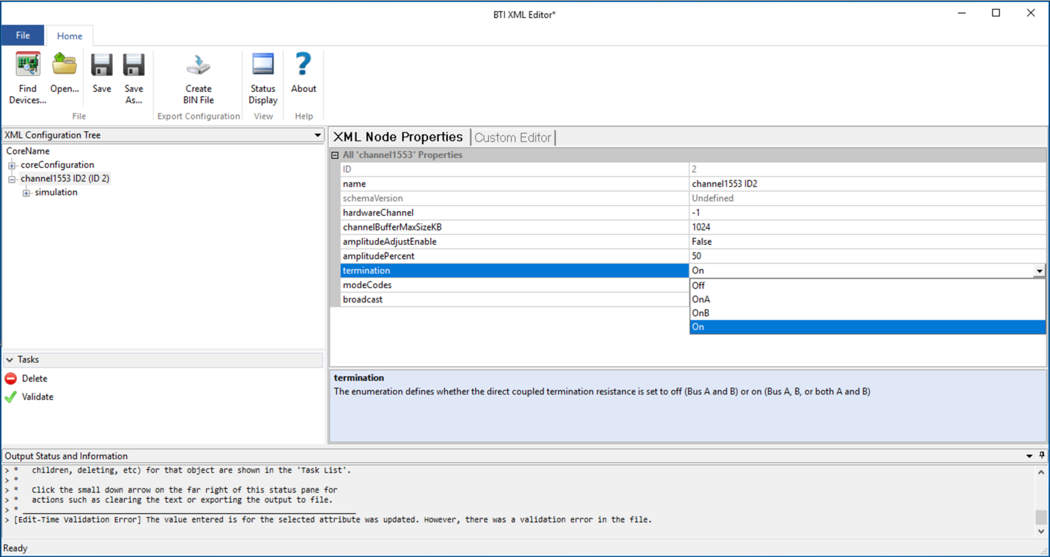
- In the BTI XML editor, navigate to the channel1553 configuration.
- Set the “termination” property to “On” for the specific bus you plan on using.
- Make the external connections between the channels you want to use.
 Transformer coupling:
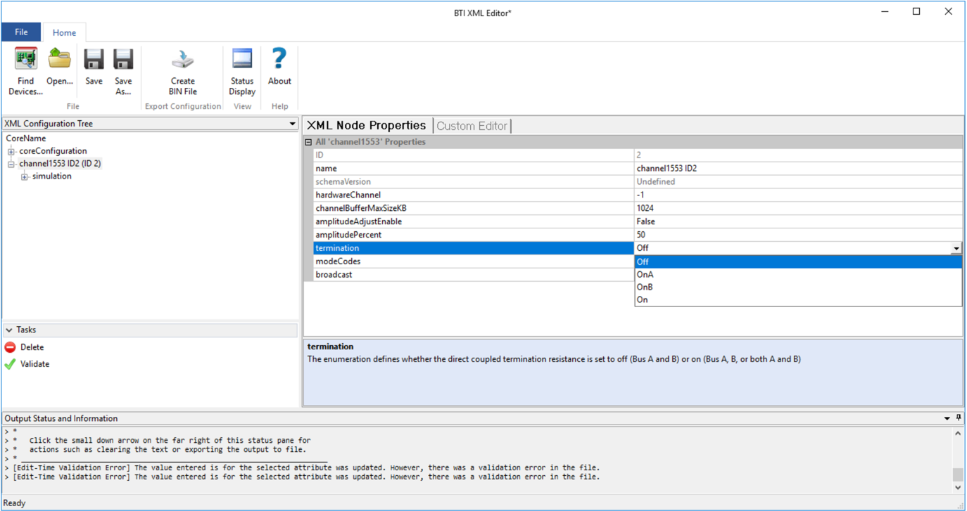
- In the BTI XML editor, navigate to the channel1553 configuration.
- Set the “termination” property to “Off.”
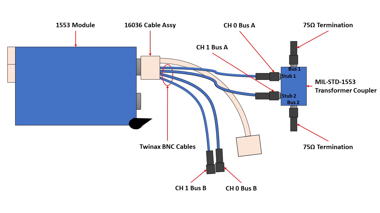
- Using the LFH 16037 Twinax BNC cables, connect channels 0 and 1 of the same bus to a 2 stub transformer coupler via the stub connections.
- Connect a 75 ohm load to each of the two bus connections.
Additional Information
Internal LoopbackThe BM, BC, and/or RT will all be simulated, so by putting these on the same channel, the other simulations can interact with each other.
Please note about making an internal connection:
- The external connection should be properly terminated in order to prevent possible damage from driving an unterminated stub.
- The messages will also be sent out to connected hardware.
- Ensure there are no external transmitters. An external BC will likely cause bus collisions and an external RT could respond and mask a configuration issue with the internal RT.
- An external monitor may be connected to analyze the complete bus traffic.
- You must have a multi-function device (LV-222-55X-XXX) to be able to simulate the BC, BM, and RT on a single channel.
- If you are using a single channel Multifunction MIL-1553 card (LV-222-550-000) you can use the shipping example - 'Example 08 - BC Control LRU RT' and simulate BC,BM and RT on single channel to perform internal loopback.
External LoopbackDirect CouplingPlease note about making the external Direct Coupling:
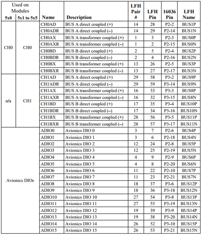
- There are no terminal blocks currently available for making these connections. This means that you’ll have to use jumper wires on the modules's LFH connector or on the D-Sub connector of the 16036 cable to make these connections
Transformer CouplingPlease note about making the external Transformer Coupler:
- This requires external hardware not included with the module or sold by NI, specifically, one 2-stub coupler and two 75 ohm terminations. The LFH 16037 cable assembly can be purchased along with the PXI MIL-STD-1553 Interface Module. The cable assembly part number is 784807-01.
- This setup only tests one bus. Swap the Twinax BNC cables to test the other bus or connect the second bus to another transformer coupler with 75Ω terminations.
- This requires a module with multiple channels per core.