Solution
The BNC-2121 has eight BNC connectors in the section labeled 14 that are directly linked to the output lines of the counters 0 and 1 of the device it is connected to, e.g. a PCIe-6612.
There are six more BNC connectors in the section labeled 15 that are wired to the spring terminal to their left (labeled 16). You can use this spring terminal to wire these BNC connectors to any PFI line of the PCIe-6612 that ends on one of the spring terminals above.
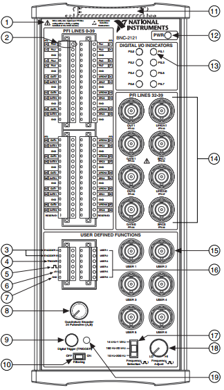
The output signals of the eight programmable counters are been output to the corresponding
OUT0,
OUT1, ...
OUT7 line. Lines
OUT0 and
OUT1 are already accessibly via a BNC connector each in the section labeled 14 in the image above.
Lines
OUT2 to
OUT7 end on the big spring terminal on the top left of the BNC-2121. Hard-wire them to the
USER 1 ...
USER 6 spring terminals to connect them to the corresponding
USER BNC connectors.