Solution
In NI-MAX, there is a
Connection Diagram tab when configuring a task that will dynamically update and display a diagram similar to that seen in the figure below, which varies depending on the strain gauge configuration selected (e.g. Quarter Bridge, Half Bridge, etc.). This connection diagram shows how to correctly wire a strain gauge to the NI-9926, NI-9944, or NI-9945.
Note: CH+ in the NI-MAX diagram is the same as IN+ on the module and in the documentation.
The accessories NI-9944, NI-9945, and NI-9926 quarter bridge completion modules have one 120 Ω, 350 Ω, and 1000 Ω quarter bridge completion resistors respectively. The resistor value in the accessory must match the resistance of the strain gauge or the readings will be incorrect.
When using a NI-9926/9944/9945 with the NI-9237, you can connect two lead strain gauges by connecting one lead to pin 0 (EX+) of the NI-9926/9944/9945 and the second lead to pin 1 (CH+ / IN+). You must also connect a wire to connect pins 1 and 2 together (CH+ / IN+ and QTR). In the case of a three-wire strain gauge, no jumper wire is needed. Instead, you can connect the third lead of the strain gauge to pin 2 (QTR).
EX+: Excitation
CH+ or IN+: Channel/Signal input
QTR: Quarter Bridge Completion Terminal
As shown below, there is a diagram in the
NI 9944/9945 Quarter Bridge Completion Accessory User Guide that labels the four-pin connections. Notice the internal resistor between EX+ and QTR that completes the bridge.
To configure the NI-9926/9944/9945, create a global virtual channel within NI-MAX by selecting Analog Signals » Analog Input » Strain. Select the NI-9237 module and appropriate channel, and name the task. Now you can configure the task using the window shown below.
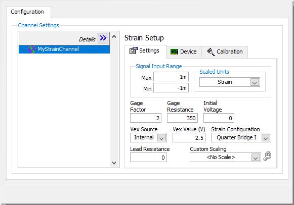
Note that if you hold your mouse cursor over the Strain Configuration field, NI-MAX will display the circuit diagram (seen below) in NI-MAX's bottom right help window.
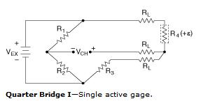
In the case above, R4 is the strain gauge, and R3 is the completion resistor provided by the NI-9926/9944/9945. All circuitry, with the exception of the strain gauge (R4), is internal.
To access the connection diagram click on the Connection Diagram tab at the bottom of the window. Follow the physical connections that are illustrated in the diagram.
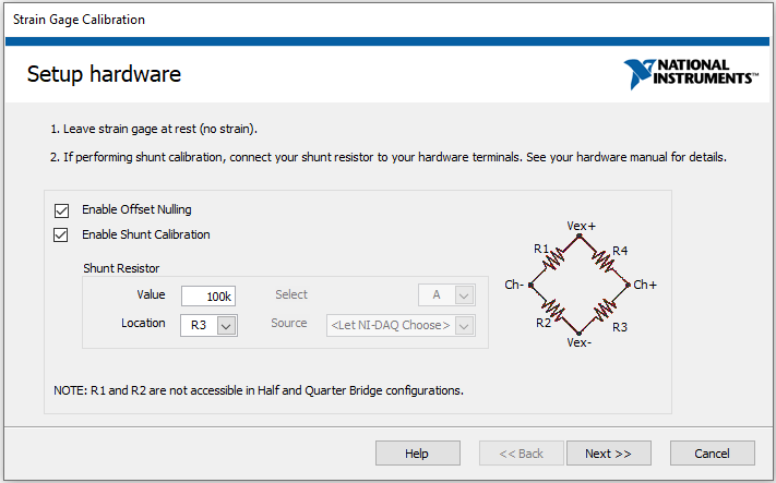
When setting up a strain task, you might consider calibrating the strain gauge. You can do this by returning to the Configuration window by clicking on the NI-DAQmx Global Channel tab at the bottom of the page. Here you can select the Device tab under Strain Settings. Now click on the Strain Calibration button. The window seen below will appear.
Note: When performing shunt calibration, the NI 9237 contains a built-in shunt resistor, which the NI-9926/9944/9945 internally hard wires across R3. You will therefore want to select R3 as the Location.
For more details about each calibration type and instructions on completing the calibration, click on the Help button at the bottom.