It is possible to import the slave device XML configuration file or copy the XML file manually to a specific location where the master tool can read it.
There are two ways for a master to work with EtherCAT Slave XML hardware description files.
- The NI Slave XML creator tool, shown below, allows the user to create an XML hardware description file based on modules and FPGA bitfile used with the chassis.
Note: Always use the XML Creator Tool installed by the latest version of the NI-Industrial Communications for EtherCAT driver available from ni.com/support.
To use the tool, follow these instructions:
- Select the modules you are using per slot.
- Check the modules used in FPGA mode. In our example this applies to module 3 and 4.
- Specify the path to your FPGA bit file (in case you are running FPGA code on your chassis). This will allow you to import the UDVs (User defined Variables) from the bit file. Leave this path blank if you do not run additional FPGA code.
- Press the Create XML File button and save the XML file to a location of your choice.
- Start over to create another XML file or press the Stop button to close the tool.
Note: If your bit file uses UDVs, they will always be assigned to Slot 1 of the chassis, so you can use only 7 modules in scan mode. That means Slot 1 must be either empty or the module in Slot 1 must be used in your FPGA code and the checkmark “Used with FPGA Mode” must be set.
Note: The XML Tool only generates the PDOs (channels) for each Object, not the SDOs (configuration). These SDOs need to be sent by the 3rd party master to the device. When using TwinCAT, this can be done in the "Startup" section of the Chassis. You can add SDO write steps there. To change configuration of a module, you need to write the index of the desired module to 0x5FFF (Value = 1..8), then write to the config-address found in the Vendor Extensions Documentation (e.g. 0x2002). After that set the 0x5FFF back to 0 and continue for the next module.
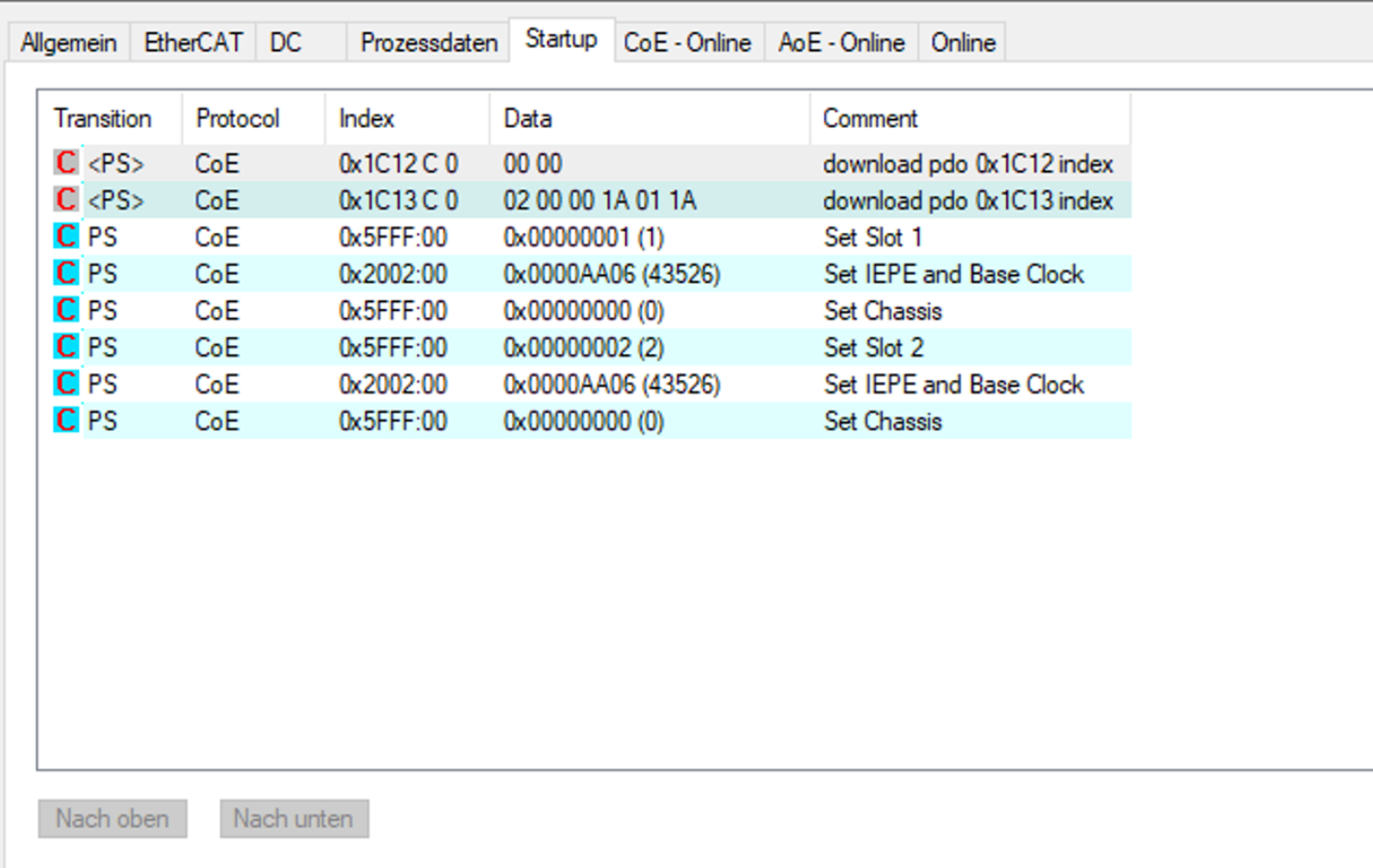
An example of a simple startup sequence that enables IEPE on all 4 Channels of two NI-9234 Modules (Slot1, Slot2). The value 43526 is the decimal representation of the appropriate bits set to 1 as found in the NI-9234 Vendor Expansion Documentation. This can be used to set Module Properties like IEPE, Differential/RSE/NRSE, Filter Options and more.
- If the 3rd party Master supports Modular Device Profile (MDP), you can easily discover the 9144 along with all installed modules and UDVs. This procedure assumes that you have installed the latest NI-Industrial Communications for EtherCAT driver.
- Copy the DD folder contents (NI-9144slots.xml and the Modules folder) from \\National Instruments\LabVIEW 201x\resource\Framework\Providers\indcomecat\DD to the third-party EtherCAT master's IO configuration folder. Find content attached to this KnowledgeBase article.
- After you successfully download a possible bitfile to your FPGA target under the NI 9144, a XML file will be generated next to the bitfile. This XML file is the User-Defined Variables profile and will have the same filename as the FPGA bitfile. The generated FPGA XML file must be copied into the Modules Folder.
- Open NI-9144slots.xml with Notepad, add the generated XML file path at the end of <InfoReference> section and save the changes. (e.g <InfoReference>Modules\example_9144_FPGA.lvbitx.xml</InfoReference>)
- Restart the third-party EtherCAT master system service. Now you can use the third-party EtherCAT master to discover the NI 9144, all modules, and possible FPGA UDVs listed under the NI 9144 slave as an 'User Defined Variables Module'.