Solution
First, the open circuit voltage of the particular Arbitrary Waveform Generator (ARB) must be known.
| ±2 V | ±10 V | ±12 V |
| PXI-5404 | PXI-5401 | PXI-5412 |
| | PXI-5411 | PXI-5421 |
| | PXI-5431 | PXI-5422 |
| | | PXI-5441 |
| | | PXI-54x3 |
The analog output of the ARB can be viewed as a ±2 V,±10 V, or ±12 V source in series with a 50 ohm or 75 ohm resistance, depending on the software setting and the specific card. You can use the standard circuit equations to determine the peak voltage/current available for a given load as seen in Figure 1.
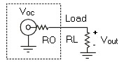
Figure 1 - ARB Output Diagram
Iout = Voc / ( RO + RL )
Iout = peak current output level
Voc = peak circuit voltage of the ARB
RL = load impedance in ohms
RO = output impedance on the ARB
For example, with the PXI-5411 driving a 800 ohm load, the maximum current sourced is approximately 10 / [800+50] = 8.31mA. In theory the PXI-5411 should deliver 200 mA when short circuited. In practice, the maximum current available is slightly lower than the calculated value for low impedance loads. Keep in mind, ARBs were not designed to drive loads less than 50 ohms.