Solution
You can generate a chirp signal by generating a phasor array with frequency and time components that are constantly changing. To do this, follow the phasor equation:
y =
A*e
(ω*t + Θ),
where A = 1, ω = 2*π*f, and Θ = 0°.
To implement this in LabVIEW, follow these steps:
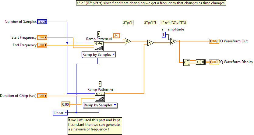
- First, generate an array of frequencies that represents all of the intermediate frequencies between the start frequency and end frequency using the Ramp Pattern VI. The number of elements in this array is equal to the number of samples you want to output on your RF device. You can multiply your transmit time by my sample rate to get the appropriate number of samples. Multiply this array by 2π to get an array that represents angular frequency (ω).
- Generate an array of time values (secs) using the same number of points using the Ramp Pattern VI. The start time should be zero, and the end time should be the duration in time of the chirp signal.
- Multiply these two arrays together to create an array that represents 2*π*f or ω*t.
- Wire this array into the phase (Θ) input of the Polar to Complex LabVIEW primitive. Use a constant to specify the r input which represents the A in the phasor equation. This will create a complex double array where each element, y, is a phasor with corresponding to a different frequency and time.