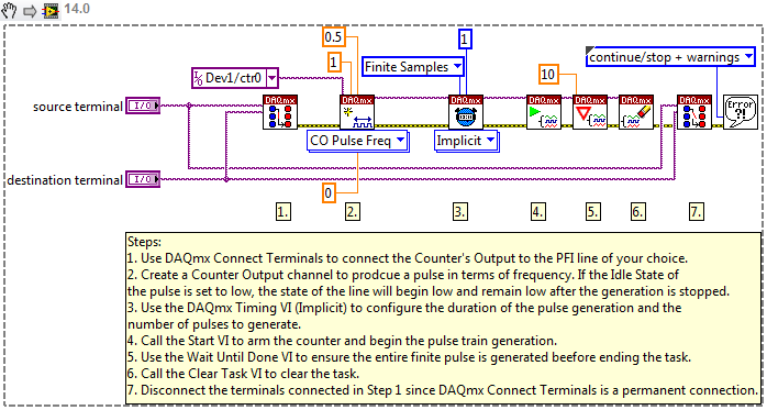
To create a trigger on the PXI(e) backplane using a multifunction DAQ device, you can generate a digital pulse and route it to the PXI(e) backplane. This functionality can easily be added to an example program. To do this, select
Help»Find Examples... from the pull-down menu in LabVIEW. Browse to
Hardware Input and Output»DAQmx»Digital Output and open
Digital - Finite Output.vi.
Modify this VI so that the counter output is routed to the RTSI bus using the following steps:
- Add a DAQmx Connect Terminals VI to the beginning of the VI, and connect the error wire to the DAQmx Create Channel VI.
- Create controls on the Source Terminal and Destination Terminal inputs.
- Right-click the Source Terminal control on the Front panel, choose I/O Name Filtering, and enable Include Advanced Terminals.
- Choose /DevX/CtrXInternalOutput as the source terminal.
- (X stands for the numbers specific to your system)
- Choose the RTSI line that you would like to trigger on as your destination terminal.
- Add a DAQmx Disconnect Terminals VI between the DAQmx Clear Task VI and Simple Error Handler VI.
- Wire the same source terminal and destination terminal controls to the DAQmx Disconnect Terminals VI.

Additional Information
To map a digital input to the PXI(e) backplane trigger, a slash (/) has to be added to the front of the I/O path.
Another way to route a trigger to the PXI(e) backplane is to use the DAQmx Export Signal VI. This VI can be used to export start triggers, reference triggers, or even sample clocks. More details on how to use this VI can be found in the Related Links Section.